
Voltage- and Current-Mode Control for PWM Signal Generation in DC-to-DC Switching Regulators
1. Oktober 2014
über
über
By Steven Keeping
Contributed By Electronic Products
2014-10-01
The controller is key to the stability and precision of the power supply, and virtually every design uses a pulse-width modulation (PWM) technique for regulation. There are two main methods of generating the PWM signal: Voltage-mode control and current-mode control. Voltage-mode control came first, but its disadvantages––such as slow response to load variations and loop gain that varied with input voltage––encouraged engineers to develop the alternative current-based method.
Today, engineers can select from a wide range of power modules using either control technique. These products incorporate technology to overcome the major deficiencies of the previous generation.
This article describes voltage- and current-mode control technique for PWM-signal generation in switching-voltage regulators and explains where each application is best suited.
Voltage-mode control
Designers tasked with building a power supply can either build a unit from discrete components (see the TechZone article “DC/DC Voltage Regulators: How to Choose Between Discrete and Modular Design”), separate controller and power components, or power supply modules that integrate both elements into a single chip.
But whichever design technique is employed, there is a high probability that regulation will employ a PWM technique of (typically) a fixed frequency. (A constant-switching frequency is desirable because it limits electromagnetic interference (EMI) generated by the power supply.)
In a voltage-mode controlled regulator, the PWM signal is generated by applying a control voltage (VC) to one comparator input and a sawtooth voltage (Vramp) (or “PWM ramp”) of fixed frequency, generated by the clock, to the other (Figure 1).

Figure 1: PWM generator for switching-voltage regulator. (Courtesy: Texas Instruments)
The duty cycle of the PWM signal is proportional to the control voltage and determines the percentage of the time that the switching element conducts and therefore, in turn, the output voltage (see the TechZone article “Using PFM to Improve Switching DC/DC Regulator Efficiency at Low Loads”). The control voltage is derived from the difference between the actual-output voltage and the desired-output voltage (or reference voltage).
The modulator gain Fm is defined as the change in control voltage that causes the duty cycle to go from 0 to 100 percent (Fm = d/VC = 1/Vramp).1
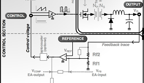
Figure 2 shows the building blocks of a typical switching regulator. The power stage comprises a switch, diode, inductor, transformer (for isolated designs), and input/output capacitors. This stage converts the input voltage (VIN) into the output voltage (VO). The voltage regulator’s control section comprises an error amplifier with the reference voltage (equal to the desired output) on one input and the output from a voltage divider on the other. The voltage divider is fed from a feedback trace from the output. The output from the error amplifier provides the control voltage (VC or “error voltage”) that forms one input to the PWM comparator.2

Figure 2: Control section and power stage of voltage-mode control-switching regulator. (Courtesy of Microsemi)
The advantages of voltage-mode control include: A single-feedback loop making design and circuit analysis easier; the use of a large-amplitude ramp waveform providing good noise margin for a stable-modulation process, and a low-impedance power output providing better cross-regulation for multiple-output supplies.
But the technique also has some notable drawbacks. For example, changes in load must first be sensed as an output change and then corrected by the feedback loop — resulting in slow response. The output filter complicates circuit compensation, which can be made even more difficult due to the fact that the loop gain varies with input voltage.
Current-mode control
In the early 1980s, engineers came up with an alternative-switching-voltage regulator technique that addressed the deficiencies of the voltage-mode control method. Called current-mode control, the technique derives the PWM ramp by adding a second loop feeding back the inductor current. This feedback signal comprises two parts: the AC-ripple current, and the DC or average value of the inductor current. An amplified form of the signal is routed to one input of the PWM comparator while the error voltage forms the other input. As with the voltage-mode control method, the system clock determines the PWM-signal frequency (Figure 3).

Figure 3: Current-mode control-switching regulator. Here the PWM ramp is generated from a signal derived from the output-inductor current. (Courtesy of Texas Instruments)
Current-mode control addresses the slow response of voltage-mode control because the inductor current rises with a slope determined by the difference between the input and output voltages and hence responds immediately to line- or load-voltage changes. A further advantage is that current-mode control eliminates the loop-gain variation with input voltage drawback of the voltage-mode control method.
Furthermore, since in a current-mode control circuit the error amplifier commands an output current rather than voltage, the effect of the output inductor on circuit response is minimized and compensation is made easier. The circuit also exhibits a higher-gain bandwidth compared to a voltage-mode control device.
Additional benefits of current-mode control include inherent pulse-by-pulse current limiting by clamping the command from the error amplifier, and simplified-load sharing when multiple power units are employed in parallel.
For a while, current-mode control looked to have consigned voltage-mode control to history. However, although they took a while to surface, engineers discovered that current-mode control regulators brought their own design challenges.
A major drawback is that circuit analysis is difficult because the topology of the regulator now includes two feedback loops. A second complication is instability of the “inner” control loop (carrying the inductor current signal) at duty cycles above 50 percent. A further challenge comes from the fact that because the control loop is derived from the inductor output current, resonances from the power stage can introduce noise into this inner control loop.3
Limiting a current-mode control regulator to a duty cycles of less than 50 percent imposes serious limitations on the input voltage of the device. Fortunately, the instability problem can be resolved by “injecting” a small amount of slope compensation into the inner loop. This technique ensures stable operation for all values of the PWM duty cycle.
Slope compensation is achieved by subtracting a sawtooth-voltage waveform (running at the clock frequency) from the output of the error amplifier. Alternatively, the compensation-slope voltage can be added directly to the inductor-current signal (Figure 4).

Figure 4: Current-mode control regulator with slope compensation. (Courtesy of Texas Instruments)
Mathematical analysis shows that to guarantee current-loop stability the slope of the compensation ramp must be greater than one-half of the down slope of the current waveform.4
There are many current-mode control regulators commercially available. Microsemi, for example, offers the NX7102 synchronous step-down (“buck”) regulator with current-mode control. The chip can accept an input range of 4.75 to 18 V and offers an adjustable output down to 0.925 V. Maximum output current is 3 A and peak efficiency is between 90 and 95 percent depending on the input voltage.
For its part, Texas Instruments offers a wide range of current-mode control regulators. One example is the TPS63060, a synchronous buck/step-up (“boost”) 2.4 MHz regulator offering an output of 2.5 to 8 V (at up to 1 A) from a 2.5 to 12 V supply. The device offers up to 93 percent efficiency and is targeted at mobile applications, such as portable computers and industrial-metering equipment.
STMicroelectronics also supplies a range of current-mode control devices including the STBB2. This is a synchronous buck/boost 2.5 MHz regulator providing an output of either 2.9 or 3.4 V from a 2.4 to 5.5 V input. The device is able to supply up to 800 mA at 90 percent efficiency and is supplied in a ball-grid array (BGA) package.
The resurgence of voltage-mode
A look through some silicon vendor catalogs reveals that voltage-mode control regulators have not gone away. The reason for this is that the key weaknesses of the previous generation of devices have been addressed by using a technique called voltage feed-forward.
Voltage feed-forward is accomplished by modifying the slope of the PWM ramp waveform with a voltage proportional to the input voltage. This provides a corresponding and correcting duty cycle modulation independent of the feedback loop.
The technique improves circuit response to line and load transients while eliminating sensitivity to the presence of an input filter. Voltage feed-forward also stabilizes the loop gain such that it no longer varies with input voltage. A minor drawback is some added-circuit complexity because a sensor is needed to detect the input voltage.
Engineers are able to select from a wide range of voltage-mode control regulators from the major suppliers. For example, Maxim offers a number of voltage-mode control devices in its portfolio including the MAX5073. This switching regulator is a buck/boost 2.2 MHz device operating from a 5.5 to 23 V supply and generates an output from 0.8 to 28 V. In buck mode, the regulator can deliver up to 2 A.
Similarly, Intersil offers the ISL9110A, a 2.5 MHz switching regulator featuring voltage-mode control. The device operates from an input voltage range of 1.8 to 5.5 V, and provides a 3.3 V output at up to 1.2 A and 95 percent efficiency.
For its part, International Rectifier supplies the IR3891, a voltage-mode control buck regulator with a wide input range of 1 to 21 V, and an output range of 0.5 to 18.06 V. The chip has a switching frequency range of 300 KHz to 1.5 MHz and can supply up to 4 A. The IR3891 features two outputs.
Choice of technology
Virtually all switching-voltage regulators employ PWM control for the switching elements. The PWM signal is either generated from a control voltage (derived from subtracting the output voltage from the reference voltage) combined with a sawtooth waveform running at the clock frequency for the voltage-mode regulator, or by adding a second loop feeding back the inductor current for the current-mode type. Modern devices have largely overcome the major drawbacks of older designs by employing techniques such as voltage feed-forward for voltage-control designs and slope compensation for current-mode units.
The result of these innovations is that engineers have a wide choice of both types of topology. Voltage-mode control switching regulators are recommended when wide-input line or output-load variations are possible, under light loads (when a current-mode control-ramp slope would be too shallow for stable PWM operation), in noisy applications (when noise from the power stage would find its way into the current-mode control feedback loop), and when multiple-output voltages are needed with good cross regulation.
Current-mode control devices are recommended for applications where the supply output is high current or very-high voltage; the fastest dynamic response is required at a particular frequency, input-voltage variations are constrained, and in applications where cost and number of components must be minimized.
For more information on the parts discussed in this article, use the links provided to access product information pages on the Digi-Key website.
References:
- “Understanding and Applying Current-Mode Control Theory - Practical Design Guide for Fixed-Frequency, Continuous Conduction-Mode Operation,” Robert Sheehan, National Semiconductor, October 2007.
- “Voltage-Mode, Current-Mode (and Hysteretic Control),” Sanjaya Maniktala, Microsemi, TN-203, 2012.
- “Switching Power Supply Topology Voltage Mode vs. Current Mode,” Robert Mammano, Unitrode, DN-62, June 1994.
- “Modelling, Analysis and Compensation of the Current-Mode Converter,” Texas Instruments, U-97, 1999.
Disclaimer: The opinions, beliefs, and viewpoints expressed by the various authors and/or forum participants on this website do not necessarily reflect the opinions, beliefs, and viewpoints of Digi-Key Corporation or official policies of Digi-Key Corporation.
Mehr anzeigen
Weniger anzeigen
Diskussion (0 Kommentare)