
Safely Measuring AC Power with Your PC's Soundcard
Simple AC power measuring system, suitable for grid and audio.
Measuring AC power with PC audio input.
I am always interested in all kinds of measurements: measuring is knowing still applies. This also applies to measuring power, what has been used, what is the yield.
AC power is the product of current and voltage at the same time.
The Soundcard Scope program by Christian Zeitnitz is particularly interesting in this case: two signals can be sampled and there is the option to display them multiplied together.
For safe operation, we must galvanically separate the signals.
Today this is no longer a major problem because there are plenty of current transformers on the market for little to very little money.
There are many types with current ranges from 5 to 50 Amp and there are also some types with a rated current of 2 mA.
In a current transformer, the secondary current is the same as the primary current divided by the transfer ratio. If the primary winding has 1 turn and the secondary winding has 1000, the output current will be 1/1000 of the primary current. 5A primary then becomes 5 mA secondary.
The voltage on the secondary side is determined by the load resistance. At 100 Ω, 5 mA gives a voltage of 500 mV.
The 2 mA current transformers have a transfer ratio of 1:1, equal windings are used for the primary and secondary, coupled by a toroidal core.
With this transformer the voltage can easily be measured by including a series resistance in the primary. Because the input current of the transformer is equal to the output current, the primary series resistance is practically in series with the secondary load resistance. Suppose the load resistance is 1 kΩ and the series resistance is 240 kΩ, then a primary voltage of 241 V gives a secondary voltage of 1 volt, but with galvanic isolation.
Current transformers have another special feature: if the secondary load is missing, the voltage across the secondary will become unacceptably high, possibly even breakdown may occur.
A current transformer should never be used without a load, on the other hand it may be short-circuited because the current is primarily determined.
A practical application is a front end for Christian Zeitnitz's Sound card Scope.
In the diagram in Figure 1, T1 is the current transformer. The diodes D1 and D2 prevent the output voltage from becoming too high if the load unexpectedly fails. The forward voltage of green or yellow LEDs is sufficiently high to have not any influence on the measuring signal. T2 is the current transformer for voltage measurement. The primary resistor is divided into several resistors so that the voltage across it also decreases.
By using either resistors R1A, R2A or resistors R2B, R1B, the phase of T2 can be switched regarding T2.
The secondary circuit is the same as that of the current transformer.
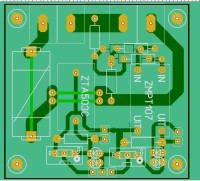
A PCB layout of this scheme is shown in Figure 2.
Then a serious warning:
There are voltage measuring modules on the market that are equipped with the above-mentioned transformer and an output amplifier.
It seems very nice, but the units in the attached photos do not meet European requirements.
A single SMD resistor is used as a primary series resistor with full primary voltage across it. If this resistor becomes defective, it is quite possible that full voltage will be applied directly to the primary winding. Furthermore, the minimum distance between the primary voltage and the secondary is much too small at 1.5 mm, which should be at least 3 or 6 mm depending on the insulation class.
In short, these units are not safe
I am always interested in all kinds of measurements: measuring is knowing still applies. This also applies to measuring power, what has been used, what is the yield.
AC power is the product of current and voltage at the same time.
The Soundcard Scope program by Christian Zeitnitz is particularly interesting in this case: two signals can be sampled and there is the option to display them multiplied together.
For safe operation, we must galvanically separate the signals.
Today this is no longer a major problem because there are plenty of current transformers on the market for little to very little money.
There are many types with current ranges from 5 to 50 Amp and there are also some types with a rated current of 2 mA.
In a current transformer, the secondary current is the same as the primary current divided by the transfer ratio. If the primary winding has 1 turn and the secondary winding has 1000, the output current will be 1/1000 of the primary current. 5A primary then becomes 5 mA secondary.
The voltage on the secondary side is determined by the load resistance. At 100 Ω, 5 mA gives a voltage of 500 mV.
The 2 mA current transformers have a transfer ratio of 1:1, equal windings are used for the primary and secondary, coupled by a toroidal core.
With this transformer the voltage can easily be measured by including a series resistance in the primary. Because the input current of the transformer is equal to the output current, the primary series resistance is practically in series with the secondary load resistance. Suppose the load resistance is 1 kΩ and the series resistance is 240 kΩ, then a primary voltage of 241 V gives a secondary voltage of 1 volt, but with galvanic isolation.
Current transformers have another special feature: if the secondary load is missing, the voltage across the secondary will become unacceptably high, possibly even breakdown may occur.
A current transformer should never be used without a load, on the other hand it may be short-circuited because the current is primarily determined.
A practical application is a front end for Christian Zeitnitz's Sound card Scope.
In the diagram in Figure 1, T1 is the current transformer. The diodes D1 and D2 prevent the output voltage from becoming too high if the load unexpectedly fails. The forward voltage of green or yellow LEDs is sufficiently high to have not any influence on the measuring signal. T2 is the current transformer for voltage measurement. The primary resistor is divided into several resistors so that the voltage across it also decreases.
By using either resistors R1A, R2A or resistors R2B, R1B, the phase of T2 can be switched regarding T2.
The secondary circuit is the same as that of the current transformer.
A PCB layout of this scheme is shown in Figure 2.
Then a serious warning:
There are voltage measuring modules on the market that are equipped with the above-mentioned transformer and an output amplifier.
It seems very nice, but the units in the attached photos do not meet European requirements.
A single SMD resistor is used as a primary series resistor with full primary voltage across it. If this resistor becomes defective, it is quite possible that full voltage will be applied directly to the primary winding. Furthermore, the minimum distance between the primary voltage and the secondary is much too small at 1.5 mm, which should be at least 3 or 6 mm depending on the insulation class.
In short, these units are not safe
Updates des Autors