
The electric meter that Matters !
Connect your electricity meter to your futuristic smart home ecosystem, thanks to the new Matter over Thread protocol !
In every building, there is an electric meter installed by the electricity company. In some countries such as France, these meters can communicate real-time data about your power consumption and total count. The total consumed energy appears on your bill at the end of the month. With my system, you can check it (and more!) at real-time, on your phone!
Picture of the project
Bill of Materials:
1. Context
A few years ago, all the French electricity counters have been replaced by the grid manager company (Enedis). They're named "Linky" and they are communicating from your house to your supplier thanks to a line carrying current. Not many people know that they can communicate to a consumer device inside the building.
Picture of the Linky
The data is transmitted from the meter through three plugs, named L1 L2 and A. The data is available between the L1 and L2 while we can get a power output between L2 and A. The signal is an UART at 9600 baud, with one start bit, 7 data bits and an even parity bit, carried on a signal at 50kHz. This data is named “TIC”, which stands for “Télé-Information Client” that we could translate to remote customer information. The power signal on its side has an RMS voltage of 6V and can supply up to 130mW. The RMS stands for Root Mean Square, which is the effective voltage equals to Vrms=Vpp/sqrt(2). If we convert it to 5V, it means that we can supply a microcontroller easily with a current of P=UI -> I=P/U=0.13/5=26mA.
More than enough for a MCU! The kind of information that can be retrieved is very wide (around 70 fields), I’ll summarize here the most interesting ones:
High level architecture of my system
2. Convert data for the MCU
The first step in the loop is to convert the data outputted from the Linky to a clean UART link that can be interpreted directly by the STM32. To do so, I designed a custom electronic circuit, inspired by some other people on the internet who tried this before.
My schematic
Above is my schematic. The signals from the electric meter enter the circuit on the connector J1. Then, I1 and A are routed to a bridge rectifier D1 and finally to a low-dropout voltage regulator UR1. Some (big) capacitors are around to make a clean signal that can resist to current consumption peaks.
On the lower side, I1 and I2 are taken to an AC opto-isolator U1 to get rid of the carrier signal. At the output of the isolator, the UART signal as we’re used to see it is there! As it’s not properly referenced to the ground, the MOS Q1 is added before the actual UART output (and it also inverts back the signal).
Finally, all of these signals are routed to a 100mil pin header that will be connected to the CN5 connector on the STM32 Dev Kit. Note that the 5V from the LDO can be separated from the 5V sent to the dev kit (and same for the GND) with jumpers. This is to be able to power the circuit from the dev kit, instead of providing power to it. I did this because the dev board consumes more energy than what can flow out of the Linky, as the display and sensors around the MCU requires to be powered. Another configuration that works is to put a 3.3V regulator on the PCB, not a 5V. Feeding the MCU power directly is possible; it can be made through the JP1 jumper to bypass all the power lines.
Schematics of the demo-kit's power lines
The PCB I designed has been made with a CNC mill. You’ll see below the expectation and the reality.
Expectation
Reality (which is quite nice)
Below are some scopes to visualize the binary signal at each step of its transformation.
Output of the LDO
Signal between I1 and I2
Signal at the gate of Q1
UART output
3. The software concept
Now that we have a physical signal available on the pins of the microcontroller, it’s time to think about the software that will make it alive, smart and useful. What I would like is that once the signal is acquired and parsed, it’s transmitted to a smart home ecosystem, without wires. Many wireless physical and application protocols exist, such as Zigbee, Z-Wave, proprietary RF, LoRa WiFi and many more. My electricity meter is in my house, which is not so big so I can exclude the long-range protocols: bye LoRa! Then I want something standard: bye proprietary RF! In general, I don’t want my smart objects to be on the WiFi network: bye WiFi! Finally, I was recently curious about the Matter over Thread protocol: we have a match!
First, Thread. It’s our RF protocol here. Wikipedia describes it well “Thread is an IPv6-based, low-power mesh networking technology for Internet of things (IoT) products.” It’s IP based so it can be connected to the internet and the other devices on the network (WiFi and Ethernet) by routing the traffic through a Border Router. It’s using the 2.4GHz frequencies range.
On top of this, the Matter application protocol is used. It was previously called Connectedhomeip. Wikipedia, again: “Matter is an open-source connectivity standard for smart home and IoT (Internet of Things) devices. It aims to improve interoperability and compatibility between different manufacturer and security, and always allowing local control as an option.” It’s a very recent protocol standardized by the CSA (Connectivity Standards Alliance) and pushed by major companies such as Apple, Amazon and Google. To make it easy, it means that thanks to Matter, you can connect a smart device from any manufacturer to any home hub and ecosystem. It’s not mandatory anymore to have the home hub from the same brand as your device. In addition, commissioning devices in a Matter network needs a manager (such as a home hub) but this is not mandatory after this. The devices in the fabric can communicate point-to-point. You already may have read articles about this recently in Elektor.
Thread network topology
Matter relies on the IP network for communication, so it can be run on devices with WiFi, Ethernet and Thread connectivity. For the commissioning process (joining a new device to the fabric), the BLE or NFC link is used. Then, our STM32WB5MM-DK is perfect, because it has the 2.4GHz capabilities for Thread and BLE.
The Matter stack is available publicly on its GitHub repo. It relies on the “Zigbee Cluster Library” to describe its clusters and attributes. The latest version of the Matter standard features some standard and wellrecognized clusters, but it’s completely possible with some development efforts to handle proprietary custom clusters. This feature is important for me as the Linky meter shows non-standard attributes.
4. The sofware in itself
The software for the MCU has been written in C and C++, while Python was used for retrieving and visualizing the data. It can be cut in four big parts:
The Matter stack available on the Connectedhomeip’s repo is generic and has to be fitted to the specific device it will be ran on. In our case, it has already been adapted to the STM32WB55 by ST and they provided this adaptation as sample projects on their public GitHub. For the STM32WB5MM-DK, we have the choice between two projects, which are a “lighting app”, simulating a light bulb, and a “window app” acting as a window opener.
This code is a very good base for my project as ST took care of making run the Matter stack on their MCU and interacting with the Thread radio. The user “just” has to write the application software, the business logic behind and update the clusters. I forked the repo and modified the lighting app to create an “electrical measurement” app from this. The project runs on FreeRTOS to handle multiple threads and dynamic memory allocation. The hardware layers have been generated with the STM32Cube suite.
The Matter stack runs in a thread of the main MCU core in parallel of the main application, while the Thread RF stack runs in the network core.
As a Matter application is about clusters and attributes, the first thing to do is to declare them to your application. To do so, the stack provides a “ZAP tool” to graphically manage the clusters and attributes then to create the corresponding C++ source files.
The ZAP tool interface
In my case, I declared the “Electrical measurement” cluster and a few of its attributes. As it was lacking some of the attributes that I was retrieving from the Linky, I created a custom cluster that I named the “Enedis-TIC”. I’ll detail this one a bit later! I won’t explain how to use the ZAP tool and the clusters of Matter because it would take hundreds of pages, It’s a very deep subject.
4.2. The UART acquisition and processing
As mentioned earlier, the decoder board streams the binary data to the MCU on an UART link, at 9600 baud with one stop bit and one even parity bit. I connected this binary stream to the pin PC0, configured as alternate function to be connected to the LPUART1 peripheral.
The UART stream starts with an ASCII STX byte and ends by an ETX byte. In between, each line starts with an LF and ends with a CR. In between, each line contains a label, may contain a timestamp then the data and finally a CRC. A schematic is worth a thousand words:
The TIC frames
I created a specific “AppLinky” class to handle the received bytes. The bytes are received in the LPUART1 Interrupt Service Routine (ISR) and stored directly in a queue only after the STX has been detected. When the frame is finished (i.e. the ETX arrived) it’s processed in a thread.
In the processing thread, it waits for the frame to be fully received. Once it is, each line is processed to interpret the kind of data that is in it. The data is stored in a big array, depending on its label. Here are (most of) the available fields:
Each data line is parsed and its data is stored in a specific object of indexed in the list of all available fields. I wrote a custom storage class to handle the different sizes of the received data fields.
It’s interesting to mention that each time a field is updated in the storage, an event is sent to notify the main thread and update the Matter cluster with the new value.
Linky thread flowchart
4.3. The Matter clusters update
However, if you’re using a standard or a custom Matter cluster, you have to set its attributes when the corresponding value changes. The Matter stack provides the setters for all these attributes so you just have to call them with the new values.
The “Electrical Measurement” cluster is not an official one yet, but it’s in the “drafts” and may be integrated in the specification in the future. It means that for now it’s not recognized by the standard smart-home hubs. In this cluster, I keep track of the current apparent power drawn, the RMS current and the RMS voltage.
In my “Enedis TIC” cluster, I keep all the fields sent by the Linky, except the date and time as my device is not supposed to be a real-time clock source.
That’s the only steps that have to be done on the device side. Once the device will be commissioned in a network, the other devices will have the possibility to subscribe to all the attributes changed it wants. But that’s for the next paragraph!
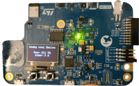
It’s also interesting to mention that when the power lines are not bypassed, the onboard OLED display is used to show the current power drawn through the electricity meter and the current RMS current.
4.4. The hub side
On this side, I could simply use an Apple HomePod/TV, Amazon Echo 4 or Nest Hub. Two things: that would be too simple for the maker I am, and also that I don’t have such. Second thing, I won a Raspberry Pi 5 from Elektor a few weeks ago.
The Raspberry as Thread border router
On this Raspberry, I’ve setup an “OpenThread Border Router” which uses a Thread dongle to extend the IP network over thread. It’s the reference implementation of the border-router concept I mentionned previously; it will handle the nodes connectivity. The installation is well-described in the wiki.
Now that the border-router is ready, I need a Matter fabric manager. I could use the official “CHIP tool” but it’s a command-line tool so it’s not very handy to use to retrieve real-time data. I found on GitHub (again) the “Python Matter Server” from HomeAssistant which can be the Matter fabric manager and can also interview and stream the nodes updates through Websockets.
My smart home ecosystem runs on OpenHab, which has no websockets native compatibility. To counter this problem, I wrote a small Python script that listens to the websocket from the server then stores the latest data and provides it through an HTTP API running with FLASK. This way, I can use the OpenHab HTTP binding to poll the API and retrieve the data to show the current and history data of my Linky in my interface.
Matter data flow
Screenshot of my OpenHab page
Screenshot of the OpenHab graphs
As you can see on the screenshots, the Linky data goes up to my OpenHab instance. I displayed some basic information, which can now be shown live or on graphs, over time. That will help me to follow my power consumption and figure out whether a device is still powered on when it’s not supposed to be.
5. Conclusion
To conclude, I reached my objective. My power consumption data is now available in real-time in my smarthome ecosystem, without need of a proprietary cloud or application.
Designing a circuit suiting my needs make it very qualitative, even if on the power supply-side it’s not ideal as a dev kit consumes much energy. Although, I’m convinced that a standalone MCU can run completely headless and powered by the electricity meter.
Exploring the Matter standard has been a very enriching experience, even if its youth makes it a bit hard to learn at the beginning. The lack of standardized clusters for my need, and data visualization tools forced me to adapt the data flow for my system, but anyway, it works!
I would like to thank Elektor and STMicroelectronics for this contest initiative.
Thanks to my fiancée for the proof-reading and tolerating my long evenings (and so short nights) in front of the computer.
I hope you, reader, have found this project interesting and/or useful!
References
Picture of the project
Bill of Materials:
- STM32WB5MM-DK
- Custom PCB
- MB1S diode bridge rectifier
- ISP814X AC Opto-isolator
- AMS117 LDO regulator
- BS170 MOS
- Resistors & Capacitors
- A building with a Linky electricity meter
1. Context
A few years ago, all the French electricity counters have been replaced by the grid manager company (Enedis). They're named "Linky" and they are communicating from your house to your supplier thanks to a line carrying current. Not many people know that they can communicate to a consumer device inside the building.
Picture of the Linky
The data is transmitted from the meter through three plugs, named L1 L2 and A. The data is available between the L1 and L2 while we can get a power output between L2 and A. The signal is an UART at 9600 baud, with one start bit, 7 data bits and an even parity bit, carried on a signal at 50kHz. This data is named “TIC”, which stands for “Télé-Information Client” that we could translate to remote customer information. The power signal on its side has an RMS voltage of 6V and can supply up to 130mW. The RMS stands for Root Mean Square, which is the effective voltage equals to Vrms=Vpp/sqrt(2). If we convert it to 5V, it means that we can supply a microcontroller easily with a current of P=UI -> I=P/U=0.13/5=26mA.
More than enough for a MCU! The kind of information that can be retrieved is very wide (around 70 fields), I’ll summarize here the most interesting ones:
- Current apparent power consumption, in VA
- Current RMS current consumption, in Amps
- Average RMS voltage, in Volts
- Total consumed power since the counter installation, in kWh My goal will be to retrieve this data and stream wirelessly to my Smart Home ecosystem. Below is the high-level architecture of my system.
High level architecture of my system
2. Convert data for the MCU
The first step in the loop is to convert the data outputted from the Linky to a clean UART link that can be interpreted directly by the STM32. To do so, I designed a custom electronic circuit, inspired by some other people on the internet who tried this before.
My schematic
Above is my schematic. The signals from the electric meter enter the circuit on the connector J1. Then, I1 and A are routed to a bridge rectifier D1 and finally to a low-dropout voltage regulator UR1. Some (big) capacitors are around to make a clean signal that can resist to current consumption peaks.
On the lower side, I1 and I2 are taken to an AC opto-isolator U1 to get rid of the carrier signal. At the output of the isolator, the UART signal as we’re used to see it is there! As it’s not properly referenced to the ground, the MOS Q1 is added before the actual UART output (and it also inverts back the signal).
Finally, all of these signals are routed to a 100mil pin header that will be connected to the CN5 connector on the STM32 Dev Kit. Note that the 5V from the LDO can be separated from the 5V sent to the dev kit (and same for the GND) with jumpers. This is to be able to power the circuit from the dev kit, instead of providing power to it. I did this because the dev board consumes more energy than what can flow out of the Linky, as the display and sensors around the MCU requires to be powered. Another configuration that works is to put a 3.3V regulator on the PCB, not a 5V. Feeding the MCU power directly is possible; it can be made through the JP1 jumper to bypass all the power lines.
Schematics of the demo-kit's power lines
The PCB I designed has been made with a CNC mill. You’ll see below the expectation and the reality.
Expectation
Reality (which is quite nice)
Below are some scopes to visualize the binary signal at each step of its transformation.
Output of the LDO
Signal between I1 and I2
Signal at the gate of Q1
UART output
3. The software concept
Now that we have a physical signal available on the pins of the microcontroller, it’s time to think about the software that will make it alive, smart and useful. What I would like is that once the signal is acquired and parsed, it’s transmitted to a smart home ecosystem, without wires. Many wireless physical and application protocols exist, such as Zigbee, Z-Wave, proprietary RF, LoRa WiFi and many more. My electricity meter is in my house, which is not so big so I can exclude the long-range protocols: bye LoRa! Then I want something standard: bye proprietary RF! In general, I don’t want my smart objects to be on the WiFi network: bye WiFi! Finally, I was recently curious about the Matter over Thread protocol: we have a match!
First, Thread. It’s our RF protocol here. Wikipedia describes it well “Thread is an IPv6-based, low-power mesh networking technology for Internet of things (IoT) products.” It’s IP based so it can be connected to the internet and the other devices on the network (WiFi and Ethernet) by routing the traffic through a Border Router. It’s using the 2.4GHz frequencies range.
On top of this, the Matter application protocol is used. It was previously called Connectedhomeip. Wikipedia, again: “Matter is an open-source connectivity standard for smart home and IoT (Internet of Things) devices. It aims to improve interoperability and compatibility between different manufacturer and security, and always allowing local control as an option.” It’s a very recent protocol standardized by the CSA (Connectivity Standards Alliance) and pushed by major companies such as Apple, Amazon and Google. To make it easy, it means that thanks to Matter, you can connect a smart device from any manufacturer to any home hub and ecosystem. It’s not mandatory anymore to have the home hub from the same brand as your device. In addition, commissioning devices in a Matter network needs a manager (such as a home hub) but this is not mandatory after this. The devices in the fabric can communicate point-to-point. You already may have read articles about this recently in Elektor.
Thread network topology
Matter relies on the IP network for communication, so it can be run on devices with WiFi, Ethernet and Thread connectivity. For the commissioning process (joining a new device to the fabric), the BLE or NFC link is used. Then, our STM32WB5MM-DK is perfect, because it has the 2.4GHz capabilities for Thread and BLE.
The Matter stack is available publicly on its GitHub repo. It relies on the “Zigbee Cluster Library” to describe its clusters and attributes. The latest version of the Matter standard features some standard and wellrecognized clusters, but it’s completely possible with some development efforts to handle proprietary custom clusters. This feature is important for me as the Linky meter shows non-standard attributes.
4. The sofware in itself
The software for the MCU has been written in C and C++, while Python was used for retrieving and visualizing the data. It can be cut in four big parts:
- The Matter stack and business logic
- The UART acquisition and processing
- The Matter clusters update
- The hub side
The Matter stack available on the Connectedhomeip’s repo is generic and has to be fitted to the specific device it will be ran on. In our case, it has already been adapted to the STM32WB55 by ST and they provided this adaptation as sample projects on their public GitHub. For the STM32WB5MM-DK, we have the choice between two projects, which are a “lighting app”, simulating a light bulb, and a “window app” acting as a window opener.
This code is a very good base for my project as ST took care of making run the Matter stack on their MCU and interacting with the Thread radio. The user “just” has to write the application software, the business logic behind and update the clusters. I forked the repo and modified the lighting app to create an “electrical measurement” app from this. The project runs on FreeRTOS to handle multiple threads and dynamic memory allocation. The hardware layers have been generated with the STM32Cube suite.
The Matter stack runs in a thread of the main MCU core in parallel of the main application, while the Thread RF stack runs in the network core.
As a Matter application is about clusters and attributes, the first thing to do is to declare them to your application. To do so, the stack provides a “ZAP tool” to graphically manage the clusters and attributes then to create the corresponding C++ source files.
The ZAP tool interface
In my case, I declared the “Electrical measurement” cluster and a few of its attributes. As it was lacking some of the attributes that I was retrieving from the Linky, I created a custom cluster that I named the “Enedis-TIC”. I’ll detail this one a bit later! I won’t explain how to use the ZAP tool and the clusters of Matter because it would take hundreds of pages, It’s a very deep subject.
4.2. The UART acquisition and processing
As mentioned earlier, the decoder board streams the binary data to the MCU on an UART link, at 9600 baud with one stop bit and one even parity bit. I connected this binary stream to the pin PC0, configured as alternate function to be connected to the LPUART1 peripheral.
The UART stream starts with an ASCII STX byte and ends by an ETX byte. In between, each line starts with an LF and ends with a CR. In between, each line contains a label, may contain a timestamp then the data and finally a CRC. A schematic is worth a thousand words:
The TIC frames
I created a specific “AppLinky” class to handle the received bytes. The bytes are received in the LPUART1 Interrupt Service Routine (ISR) and stored directly in a queue only after the STX has been detected. When the frame is finished (i.e. the ETX arrived) it’s processed in a thread.
In the processing thread, it waits for the frame to be fully received. Once it is, each line is processed to interpret the kind of data that is in it. The data is stored in a big array, depending on its label. Here are (most of) the available fields:
- Meter’s address
- Consumed energy distributor index 1-4
- Current apparent power
- Data (TIC) version
- Total injected energy
- Current apparent power lines 1-3
- Date and time
- Total reactive energy Q1 to Q4
- Average voltage lines 1-3
- Supplier’s calendar name
- RMS current line 1-3
- Status register
- Current supplier’s price tag
- RMS voltage line 1-3
- Start/end of peak 1-3
- Total consumed energy
- Apparent reference power
- Info messages
- Consumed energy supplier index 1-10
- Apparent cutting power
- Delivery location code
Each data line is parsed and its data is stored in a specific object of indexed in the list of all available fields. I wrote a custom storage class to handle the different sizes of the received data fields.
It’s interesting to mention that each time a field is updated in the storage, an event is sent to notify the main thread and update the Matter cluster with the new value.
Linky thread flowchart
4.3. The Matter clusters update
However, if you’re using a standard or a custom Matter cluster, you have to set its attributes when the corresponding value changes. The Matter stack provides the setters for all these attributes so you just have to call them with the new values.
The “Electrical Measurement” cluster is not an official one yet, but it’s in the “drafts” and may be integrated in the specification in the future. It means that for now it’s not recognized by the standard smart-home hubs. In this cluster, I keep track of the current apparent power drawn, the RMS current and the RMS voltage.
In my “Enedis TIC” cluster, I keep all the fields sent by the Linky, except the date and time as my device is not supposed to be a real-time clock source.
That’s the only steps that have to be done on the device side. Once the device will be commissioned in a network, the other devices will have the possibility to subscribe to all the attributes changed it wants. But that’s for the next paragraph!
It’s also interesting to mention that when the power lines are not bypassed, the onboard OLED display is used to show the current power drawn through the electricity meter and the current RMS current.
4.4. The hub side
On this side, I could simply use an Apple HomePod/TV, Amazon Echo 4 or Nest Hub. Two things: that would be too simple for the maker I am, and also that I don’t have such. Second thing, I won a Raspberry Pi 5 from Elektor a few weeks ago.
The Raspberry as Thread border router
On this Raspberry, I’ve setup an “OpenThread Border Router” which uses a Thread dongle to extend the IP network over thread. It’s the reference implementation of the border-router concept I mentionned previously; it will handle the nodes connectivity. The installation is well-described in the wiki.
Now that the border-router is ready, I need a Matter fabric manager. I could use the official “CHIP tool” but it’s a command-line tool so it’s not very handy to use to retrieve real-time data. I found on GitHub (again) the “Python Matter Server” from HomeAssistant which can be the Matter fabric manager and can also interview and stream the nodes updates through Websockets.
My smart home ecosystem runs on OpenHab, which has no websockets native compatibility. To counter this problem, I wrote a small Python script that listens to the websocket from the server then stores the latest data and provides it through an HTTP API running with FLASK. This way, I can use the OpenHab HTTP binding to poll the API and retrieve the data to show the current and history data of my Linky in my interface.
Matter data flow
Screenshot of my OpenHab page
Screenshot of the OpenHab graphs
As you can see on the screenshots, the Linky data goes up to my OpenHab instance. I displayed some basic information, which can now be shown live or on graphs, over time. That will help me to follow my power consumption and figure out whether a device is still powered on when it’s not supposed to be.
5. Conclusion
To conclude, I reached my objective. My power consumption data is now available in real-time in my smarthome ecosystem, without need of a proprietary cloud or application.
Designing a circuit suiting my needs make it very qualitative, even if on the power supply-side it’s not ideal as a dev kit consumes much energy. Although, I’m convinced that a standalone MCU can run completely headless and powered by the electricity meter.
Exploring the Matter standard has been a very enriching experience, even if its youth makes it a bit hard to learn at the beginning. The lack of standardized clusters for my need, and data visualization tools forced me to adapt the data flow for my system, but anyway, it works!
I would like to thank Elektor and STMicroelectronics for this contest initiative.
Thanks to my fiancée for the proof-reading and tolerating my long evenings (and so short nights) in front of the computer.
I hope you, reader, have found this project interesting and/or useful!
References
- GitHub repository of the project - https://github.com/BDeliers/stm32wb-matter-device-over-thread
- My Website - https://www.bdeliers.com
- An inspiring schematic - https://github.com/papsdroidfr/Linky/blob/main/_docs/schemaLinky.png
- Matter’s website - https://csa-iot.org/all-solutions/matter/
- Thread’s Wikipedia page - https://en.wikipedia.org/wiki/Thread_(network_protocol)
- Matter standard’s Wikipedia page - https://en.wikipedia.org/wiki/Matter_(standard)
- Enedis TIC datasheet - https://www.enedis.fr/media/2035/download
- Python-matter-server library - https://github.com/home-assistant-libs/python-matter-server
- OpenThread border router - https://openthread.io/guides/border-router
- Connectedhomeip repository - https://github.com/project-chip/connectedhomeip
- STM32WB5MM-DK product page - https://www.st.com/en/evaluation-tools/stm32wb5mmdk.html
- STM32WB5MM-DK schematics - https://www.st.com/content/ccc/resource/technical/layouts_and_diagrams/schematic_pack/gr oup1/0a/d5/78/b6/d7/bd/45/de/mb1292_shematics/files/MB1292-WB5MMB01_Schematic.PDF/jcr:content/translations/en.MB1292-WB5MM-B01_Schematic.PDF
- OpenHab - https://www.openhab.org/
Build This Project
Bring this design to life with the Elektor PCB Service, powered by Eurocircuits. Upload the project files and order professionally manufactured PCBs or assembled boards through a proven European production platform.
Supporting KiCad, Eagle, Gerber, and ODB++ formats, the service is suitable for everything from prototypes and validation builds to series production and volume manufacturing.
Made in Europe. Fast. Reliable. Professional.
Diskussion (0 Kommentare)