
Long Interval Timer
The timer can be set for long intervals of hours to days or even months with relatively high time accuracy.
Introduction
The timer was originally used as a reminder to wind old wall clocks. In this case, the interval is 10 days.
I looked for suitable circuit in many sources but could not find any. Many timers are available, with 555, Op. Amps, with transistors, counters and so on. Problem is always a relative complexity, a large value of the capacitors and less accuracy is associated with it.
Suggested circuit is very simple. Requirements are:
- low current and power consumption
- accuracy of time
- simplicity
- time interval adjustable in days
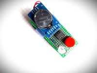
Parts
There are just a few components, see schematic.
- U1 microprocessor ATtiny85, DIL package
- U2 real time clock module DS3231
- R1 resistor
- BP push-button switch
- LED1 Led diode 10mm
- battery holder 2xAA battery or other, 3 to 3.3V
Description of circuit
Circuit is based on microprocessor ATtiny85. Precise time is provided by real time clock module DS3231. Its SQW output, according to alarm conditions, generate pin change interrupt to microprocessor, pin 6. Others output from DS3231, SDA and SCL deliver time and date data for ATtiny85. Communication is done by I2C protocol. Both pins contain internal pull-up resistors. Alarm Led and Push-button are connected to inputs, pin 2 and pin 3.
Microprocessor is running in two modes: ATtiny 85 is in the most time in sleep mode. (during long interval, for instance 10 days). After adjusted number of days and exactly in certain time, the real time clock DS3231 initiate pin change interrupt and MCU is awakened. Alarm LED start flash, remind that is right time to wind up clock or do something else. This interval is short, it is awake mode, and after pushing button the mode is change back to sleep mode.
The first time, if circuit is connected to battery, diode is flashing and expect push-button be pressed.
Required voltage is 3 V to 5 V and current consumption is about 0.4 mA (3 V). Two classic powerful 1.5 V alkaline batteries with 3000 mAh can last half an year theoretically. Problem is voltage level. From initial about 1,6V is soon voltage bellow 1.5 V and less, that is 3V for two cells. This is not enough, ATtiny and RTC do not like voltage bellow 3V. Alkaline batteries I do not recommend.
The best batteries are lithium. One 3.7 V battery can last more than 6 month. Very good battery alternative is LiFePO4, one cell. Voltage is 3,2V and very stable for long time.This battery can last more than 12 months.
In the last time, there is a new type rechargeable Li-ion AA 1.5 V battery available, with even more capacity than 3000 mAh. Voltage level is stable 3 V during long time. Two batteries can last longer. In describe project I have use Li-ion rechargeable 1,5 V batteries, type AA. If alarm is active, during awake time, discharged battery could be replaced. The current time and all settings remain, thanks to the backup battery.
To reduce power, LED1 indicator located directly on module DS3231 should be disabled. Carefully remove diode D1 or its resistor R4. (Circuit diagram for DS3231.) Remove D1 or R4 on module as well. This step disable charging circuit if backup battery is not rechargeable.
Many articles available on internet are concerning current reduction for RTC module DS3231. This way could be interval for battery replacement prolonged.
My construction was done on universal double sides prototype board. If you want to make it on dedicated PCB, gerber file is attached. Plastic battery holder is fixed to PCB by binding tape.
Software
Software is located in Arduino ino file.inside attached Reminder.zip. For programming ATtiny should be used Arduino board or programmer.. In next lines are steps how to do it:
In File Preferences, Additional Board Manager must contain URL for ATtiny. If not, copy following link: https://raw.githubusercontent.com/damellis/attiny/ide-1.6.x-boards-manager/package_damellis_attiny_index.json
Arduino should be connected to ATtiny via programmer or without programmer by wires: How to programming via Arduino
- pin 10 Arduino..........pin 1 ATtiny 85
- pin GND......................pin 4
- pin 11..........................pin 5
- pin 12...................... ...pin 6
- pin 13..........................pin 7
- pin 5V..........................pin 8Programming procedure is as follows:
- Arduino IDE without programming tool, select board Arduino Uno. Choose FILE........EXAMPLES.......ARDUINOISP......UPLOAD
- Connect Programming Tool with ATtiny 85, select board Attiny 85, Clock 8MHz, Processor 85. In IDE select TOOLS ......PROGRAMMER "Arduino as ISP", than select TOOLS....Burn Bootloader.
- Now is ATtiny ready for sketch.
- Upload tab "Scetch". At first, check, if board is ATtiny 85 and than upload code. Be careful, Upload should be done from Scetch, by "Upload using programmer".In attached file, there is software code - ino file for the the Reminder.
Adjustment of interval in 10 days is on line 115: "alarmDay = (dayMonth + 10);".
In line 120: "myRTC.setAlarm(DS3232RTC::ALM2_MATCH_DATE, 10, 19, alarmDay);" is set time 19:10 at which is alarm activated in 10th day. For different intervals class variable must be changed according to JChristensen's library for DS3232.
Before programming ATtiny 85, there is necessary to adjust actual time for module DS3231. At Arduino web pages are examples how to do it, or you can use attached zip file DS3231 Time Set.
Conclusion
Improvement could be done in current consumption. For father reduction of DS3231 consumption, there are some articles on internet. Current for Alarm led can be decrease as well, by choosing better intervals of alarm. Such way battery selection could be simplified.
The timer is usable for any application requiring a long time interval. In the case of extra long time for reminding, we have to remember what is actually remind us of!
Want to build a project?
Bring your design to life with the Elektor PCB Service, powered by Eurocircuits. Upload the project files and order professionally manufactured PCBs or assembled boards through a proven European production platform.
Supporting KiCad, Eagle, Gerber, and ODB++ formats, the service is suitable for everything from prototypes and validation builds to series production and volume manufacturing.
Made in Europe. Fast. Reliable. Professional.
Diskussion (1 Kommentar)