
Remake Elektor weather station
Lab Team Note: This project no longer supported, but comments are always welcome. New improved version of the ESP32 Weather Station [180468] We keep the ESP32 and added the wishes and request we got for the old one
[Firmware]
- User contributed firmware for ESPHome by hugokernel can be found here: https://github.com/hugokernel/esphome-weather-stationThe current firmware presented in this article does not receive any other main updates at the moment. We try to do some maintenance, but we recommend to use the user contributed replacement firmware for ESPHome from hugokernel for the station.
This a remake of the Weather Station published in the January 2019 issue of ElektorLabs. There were some issues with this project -both in hardware and software- that needed to be tackled. Also we got request of adding a few functions to the station that can't be done with the current PCB anymore without heavy soldering. That's why we decided to revise the hardware completely, keep the sensors (and add some more sensors) and rewrite the firmware to make improve the functionality of the weather station. The housing is now more complact and wireing may be take a bit longer. But in the end results can be really nice looking


[Parts]
- The display used is a HD44780 2x16 character LCD with an I²C backpack you can find for various Arduinboards running at 5 volts e.g on the Elektor StoreDisplay (2*16) https://www.elektor.de/2x16-character-lcd-blue-white-120061-77
I²C Backpack https://www.elektor.de/iic-i2c-serial-interface-adapter-module
- The µSD-Card socket used is a third party product that can be order from the Elektor Store (https://www.elektor.de/minisd-card-module)
We know that the BOM is not easy to be sourced within the Elektor shop. If you have any questions please leave a comment.
[Current Projectstate]
- Currently this project is in Maintanancemode. Not big updates or heavy improvements are currenlty planned.[Update 3.12.2019]
We have the set of feature ready for now. The PCB in the cylindric part of the plastic ( the barometer one ) will not be used and replaced with our own PCB. For more comfort you can still use the connectors as they will also be there and just move from there to the ESP32. This new PCB also now houses a proper place for the BME280 from the Elektor Shop, so no longer big amounts of hot glue are required to place it. Also we plan to add a second sensor connector for a pure pressure and temperature sensor. All connections to the sensors are made with I²C, besides the plastic parts for the windspeed , direction and rain amount. We will keep the signals and connect them directly to the ESP32.
This will result in 7 wires required here, VCC ( we used 5V and a LDO to get 3.3V ) , GND, RAIN, WINDSPEED, WINDDIR, SDA and SCL. This means you can use cheap 8 wire cables like those found in ethet ones to connect the station to the ESP32.
For the ESP32 we changed the enclosure. With the last one it was a bit tricky to get the cables waterproof to the inner. We now have a enclosure with predefined breakout points for the cables and a transparent cover, so you can see inside the station. And here come a few changes.
The last station had a kind of charging circuitry for solar panels and lead battery cells. As solar charger are now not that expensive any more and will do a much better job that the simple components used in the old station, we removed this completely. Instead we setup a proper under voltage lockout, so that your batteries won't get deeply discharged over time.
The power input will still be 7 to 12 Volt and using a DC / DC converter build up from THT parts. What is added is a little I2C LCD ( 2x16 Character ) as option and also some buttons for navigation. We added a sd-card slot, so you can write the data to a sd-card for later use or storage.
Something else? Yes, we reserved a bit of space for a LoRa-Module ( RFM95 ), so you can send Data also using LoRa or even LoRaWan. This means the station can gain a bigger range than with the WiFi alone.
Last but not least you can connect a particle sensor to the station. This can be a SDS011 or a HPMA115S0-XXX. We may add more sensors later, but for now that shall be enough in the beginning.
Software will be changed to accommodate for the new hardware attached to it, but all drivers that were inside the old station will be included into the new one. As we have a spare Pin left in the Cable and some spare pins on the ESP32 we can also consider adding a DS18B20 pin to the station.
The main problem of the ESP32 Pico Kit board still is power consumption, as these will be at 100mA average at 5V input. This is due to the ESP32 and the WiFi and 25mA will be drawn useless from the USB-Serial converter on the board, as the shutdown pins are not connected, nor they can be controlled form the ESP32 without soldering.
To get power consumption less worse we will add a start / stop mechanism to the WiFi that it is only activated if the station needs to send data. This will also mean that, if this mode is activated the usual config via WiFi won't work any longer.
So as you can see we have some work to do now, to make the new station ready in time for the spring season. The good thing is that those who already have a station can mostly swap the PCB as we keep the Pico Kit as its main MCU.
[Update 9.12.2019]
The basic bits for the rain and wind sensor are done and the PCB is on its way. The next thing will be the WiFi, as we will add the start - stop mode and the data upload. Also the LMIC has been implemented to allow LoRa communication, but the LMIC and the ESP32 are not really friends, as the RTOS sometimes causes a bit of a hassle.
[Update 11.12.2019]
So far drivers for the HPM115S0 and SDS011 are implemented and working. For the SDS011, the last one we had in the lab sadly has a mail function, as the fan is not working or we send actually the command for self destruct. The HPM115S0 form Honeywell is working and an abstraction lays let the software switch for both parts without heavy code changes. This also means we can support more particle sensors in the future.
For the I²C Bus we have now basic support for:
- BME280 ( 0x77 / 0x76 )
- Wuerth WSEN-PAD ( 0x5C / 0x5D )
- Veml6070 ( 0x38 )
- TSL2561 ( 0x29 / 0x39 / 0x49 )
- VEML6075 (0x10)
- TSL2591 ( 0x29 )
Next thing will be the wifi and the start stop mode. Also on tge todo list is 1-Wire for DS18B20 sensors.
[Update 19-12-2019]
Hardware
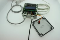
This project is split up into three PCBs: the main board 191148-1 that will be installed in a waterproof case outside, but close to your house and the connector board 191148-2 that fits into the case of the thermo-hygro sensor and replaces its internal hardware. It also provides RJ11 sockets for connecting the wind and rain sensor modules of our weather station. The boards are interconnected with a 7-wire cable, an 8-wire ethernet cable will do fine.
The first board contains the power supply and its protection circuitry (T1, IC1 and MOD1), an ESP32 Picokit module (MOD2), a micro SD card connector for data logging (K5), a 2 x 16 character LCD with I2C interface (K6), an optional RFM95 break out board for LoRa connectivity (MOD3, not supported yet!), connections to the second board (K2, K3, K4) and to a Honeywell particle (dust) sensor (K7 and K8). The latter may easily be damaged by frost and therefore we didn’t connect it to the thermo-hygro sensor case, which must be installed in more open space, not too close to the house.
The third PCB (191148-3) is more like an adapter for mounting and connecting the Honeywell HPMA115 dust sensor, so it can easily be fixed in the same type of case as the weather station’s main PCB.
Main board 191148-1
The weather station is (normally) powered by a 12V rechargeable battery, which is charged by a solar panel and an external solar charger.
T1 and R3 serve as polarity protection, the MOSFET will only conduct if the battery terminals are connected the right way.
If -for whatever reason- the charging process doesn’t produce enough energy to compensate for the power dissipated by the weather station, this battery must be disconnected to prevent deep discharge and damage. For this task we selected a good old programmable voltage detector ICL8212, or rather its CMOS successor MAX8212 from Maxim Integrated. With only three external resistors for adjusting thresholds/hysteresis and an external p-channel MOSFET as switch it does exactly what we want: deep discharge protection for the battery.
With the current values for R2, R8 and R4 we have an undervoltage lockout, that switches off the battery when its voltage drops below 10.5V and switches it on again when it rises above 11.1V.
Power supply
A DC/DC converter (MOD1) steps the 12V battery voltage down to the 5V supply voltage for this project, LED1 is the power on indicator. The ESP32 Picokit module has an internal 3.3V regulator, its output is routed to pins 18 and 21 of this module and these pins supply the 3.3V needed for the circuit on the main board.
ESP32 Pico Kit module
This is of course the ‘brains’ of our weather station. It controls and reads out the sensors, displays information on the LCD, logs data on the SD card and communicates with an (indoors) computer via WiFi (or Lora, when implemented). It also contains a reset and a user button, plus a USB connection for flashing the weather station’s firmware.
I2C bus
This bus is used for communication with the LCD and air pressure/temperature/humidity sensors, but of course it can also accommodate other I2C compatible sensors or devices you may want to add to the weather station. In ‘normal’ operation jumpers JP1 and JP2 must be closed to provide the pull up resistors (R5 and R6) that are needed for this bus. If you connect an I2C device that already contains pull ups on the bus connections, you may either omit R5 and R6 or open the jumpers.
The LCD module also uses the I2C bus, with jumper JP3 you can select the appropriate supply voltage for this module, depending on the brand/model of the LCD, either 3.3V or 5V.
SD card
For the micro SD card connector we have chosen a small breakout board that is available in the Elektor shop, with a 100mil pitch pin header that can easily be soldered/connected to our main PCB. This BOB must be mounted perpendicular to the main board in order to access the card, you can either replace the straight pin header with an angled type or use pliers and some force to bend the pins 90 degrees. Be careful not to damage this small board, though!
Connector board 191148-2
Although this board also accommodates the pressure/humidity/temperature sensor (module), it mainly serves as connection between the ESP32 and the sensors of our weather station. It replaces the redundant board inside the thermo/hydro unit that is provided with the WH-SP-WS02 outdoor kit and fits perfectly inside its case.
The 3.3V LDO IC1 is the only active component on this PCB, apart from the three pull-up resistors R1 to R3 for the switches in the rain and wind sensors there are only connectors for the sensor modules used in the weather station.
The RJ-11 sockets connect to the wind (K4) and rain (K2) sensors, their positions correspond to the holes in and text on the case of the thermo/hydro unit.
Just like in the earlier version of our weather station, an Elektor BME280 breakout board can be used as temperature, relative humidity and air pressure sensor module at position MOD1 on the PCB. The numbering of the pins on this PCB matches the pin numbers on the breakout board. Alternatively, if you prefer to use a different brand of I2C environmental sensor module, you can connect it to MOD2 and omit the BME280 BoB at MOD1.
[Update 14.01.2020]
Software makes progress but some things may need to be finished later. Currently all the drivers we support with the old station are included and seem to work, also we have now for the particle sensors an autodetect feature in place that will decide if we have a SDS011 or HPMA115S0 attached to the serial port and automatically choose the appropriate driver. One thing that is interesting are the well-priced Chinese i²C LCD Backpacks, those run with 5V and could in theory opperate on a 3V3 I2C bus. As you get sometime more than you paid for we have here included pull-up resistors on the PCB that pull up to 5V, not that healthy for the ESP32, even if it works in the long run.
Also the Web interface got a "small" overhaul:

Still work in progress but getting closer to finish. Also, we will add the firmware from the former Weather station so that you can choose in the first place what you like more. And also, we are testing the new firmware for the older hardware.
[Update 19.03.2020]
Firmware now reached Version 1.1 and fixes a few bugs that were found. First the ArduinoOTA service will not work if the EPS32 is in AP mode, resulting in a Core panic and a restart loop. Also for the AP mode only the webserver will start, all other services like MQTT , openSenseMap will not be started as usually they can't connect to their servers. This will reduce CPU load while in AP mode. Somthing strage is the ESP32 webserver when running in AP mode. If you connect with a current Chrome, Internet Explorer or Vivaldi, those browser will have trouble louding multiple files from the webserver at once. Firefox currenty runs fine. This happens only in AP mode, if the station is running as WiFi Client the mentionend browsers work just fine.
This minimize the effect in AP mode, the website has been optimized to have all javascript and html in one file, this helps to get the station configured. Something else new is the way the firmware now handels updates. You can now upload a new binary via "Update Firmware" and also upload the webpages with "Update Webages". Both options requiere a binary file. While it is easy to generate the firmware itself, the webpages requiere a bit more work and will be discussed later. Also some minor tweeks are now in place to reduce the amount of serial messages generated by the station. Currently it is investigated if a small serial and telnet command interface can be integrated into the firmware.
Still on the wishlist is OneWire support. The station itself has been prepared for that and the connections on the PCB are already in place, "only" softwaresupport needs to be added, but it is on it's way. A bigger step will be the LoRa integration, as the ESP32 has for LoRa a horrible timing and if we use the LMIC this is a kind of awfull combination in the first place.
[Update 18.09.2020]
It has been a while, but we updated the firmware in the meantime have now reached version 1.5. May thanks to our readers and those who reported all the misshaps left in the code. The code is not perfect as many things, as with all projects, can be still imroved. For the Version 1.5 the biggest change is the move away from the ArdoinoIDE to the more coding fiendly Visual Studio Code with the PlattfromIO addition. This means that you still can compile the code with the ArduinIDE, but there will be hurdles arround.
Also with the move to PlatformIO we can provide a set of librarys that will compile with the current code fine to avoid problems due to bugs in external librarys for now. But first what has changed:
Version 1.5
- Fixed a bug where the MQTT component had no access to inernal sensordata
- Updated TLS2591 library and worked arround a bug inside
- Fixed the accumulation of rain and rain per hour
- Preparation for M5Stack support
Version 1.2
- Fixed a bug with VEML6075 and VEML6070 driver stack, not correctly reporting the sensors
For the WebUi we have fixed a bug with the temperature gauge, where the needle is not showing the right temperature. At the momentet we don't provide binary files for the firmware but this will be added soon again. Something you can see from the changelog is that we are going to support the M5Stack ( https://www.elektor.com/m5stack-esp32-basic-core-development-kit ). This is experimental and will not be included for the moment in the officail code. But on GitHub you'll find soon a new branch of code for the M5Stack, also adding new supported sensors to the system. The Update prgress may be a bit slow in the last months but the station is still patched, bugs are fixed and where possible improvment included. If the firmware works as expeceted we may do a packport to the old station with a reduced featureset, but this is something for a future update.
Diskussion (33 Kommentare)