
Pulsing Led for Competition
A simple LED pulsing circuit using easily available components: one dual op-amp, 7 resistors, two diodes and a capacitor (and the LED!).
When I saw the Elektor Pulsing LED competition I wasn’t thinking about winning – I very rarely win anything and there are better brains than mine out there – but it was a nice challenge and though it’s easy to do this with a small microcontroller, I agree with the organisers’ sentiments that it’s nice to do things in analog sometimes. So here goes. My aim was to keep it as simple as possible, consistent with good design.
One of the basic op-amp circuits that one learns about is the op-amp astable. This charges and discharges a capacitor and produces a square wave output, but the capacitor waveform can also be used – it’s not a true sawtooth but for our purposes it is fine.
When using single supply the choice of op-amp is important, because you want things to work down to ground. The LM358 is a good choice for my circuit. The common-mode input range goes right down to the negative rail (ground on a single supply). The output is almost rail to rail, and can supply a minimum of 10-20 mA of current, enough to light a LED. And there are 2 op-amps in it, one to oscillate and one to drive the LED. So far, so good.
I used the capacitor voltage from the first op-amp used as an astable to drive a constant current source on the second op-amp. Why a constant current source? The LM358 can supply up to 40mA, too much for a small LED. Because of the long time constant needed (a few seconds) the capacitor charge-discharge resistor of the astable is quite high and I couldn’t load it too much.
I did the development with the aid of my National Instruments MyDAQ. This is a general purpose data acquisition device analog and digital inputs and outputs. It also has a 5V power supply available (powered from its USB connection) and also +/-15V. Since the current available from the +/- 15V supplies is quite limited, I chose to try to use the 5V supply. So my current sensing resistor is 47ohms, which will get around 1V across it at a maximum LED current of 20mA. That’s not to say you couldn’t use a higher voltage (12V) and I’ll discuss this later.
Looking at the circuit diagram (Figure 1), R1 is the capacitor charge/discharge resistor. To make the pulsing rate variable, I’d suggest changing this to a 47K resistor in series with a 220K variable resistor (usually a preset). R2 and R3 are the voltage divider for the non-inverting input of the astable, with positive feedback via R4 and D1. D1 pulls the non-inverting input down to almost ground, and since the capacitor voltage follows this, the varying capacitor voltage will go down to nearly ground as well. I have specified a schottky diode for D1 so that this voltage is as near as possible to ground, but in my initial prototype I used a germanium diode which worked just as well.
Astute readers may notice that the op-amp pin numbers are the same for both op-amps – this is due to my not knowing how to get the second op-amp on my drawing program, and I’ll correct this when I can.
R5, D2 and R6 feed the constant current LED circuit. D2 drops any residual voltage on the capacitor waveform at minimum so that the LED current gets to zero at minimum brightness. Again, you could make the brightness of the LED variable by changing R6 to a 220K resistor and a 470K pot. And if you are working the circuit from 12V then I would suggest changing R5 to a 2.2M to avoid overdriving the LED. If you want to have a “full on” setting, apply a switched 5V (or 12V…) via a resistor of the same value as R5 to the anode of D2. You can use a PNP transistor to do this if necessary.
So we have a simple circuit using easily available components that only uses one dual op-amp, 7 resistors, two diodes and a capacitor. I constructed my prototype out of components I had on hand.
Figure 2 shows the waveforms of the circuit, at the capacitor and the output of the astable op-amp. The NI MyDAQ is not good at extra low frequecies do I used a smaller capacitor to increase the frequency for this screen capture.
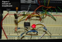
Figure 3 is a photo of my (rather messy) breadboard construction of the circuit.
The circuit works well considering its simplicity. I have been busy and almost did not get it posted. I may expand on it and post improvements after the Pulsing LED competition is over.
One of the basic op-amp circuits that one learns about is the op-amp astable. This charges and discharges a capacitor and produces a square wave output, but the capacitor waveform can also be used – it’s not a true sawtooth but for our purposes it is fine.
When using single supply the choice of op-amp is important, because you want things to work down to ground. The LM358 is a good choice for my circuit. The common-mode input range goes right down to the negative rail (ground on a single supply). The output is almost rail to rail, and can supply a minimum of 10-20 mA of current, enough to light a LED. And there are 2 op-amps in it, one to oscillate and one to drive the LED. So far, so good.
I used the capacitor voltage from the first op-amp used as an astable to drive a constant current source on the second op-amp. Why a constant current source? The LM358 can supply up to 40mA, too much for a small LED. Because of the long time constant needed (a few seconds) the capacitor charge-discharge resistor of the astable is quite high and I couldn’t load it too much.
I did the development with the aid of my National Instruments MyDAQ. This is a general purpose data acquisition device analog and digital inputs and outputs. It also has a 5V power supply available (powered from its USB connection) and also +/-15V. Since the current available from the +/- 15V supplies is quite limited, I chose to try to use the 5V supply. So my current sensing resistor is 47ohms, which will get around 1V across it at a maximum LED current of 20mA. That’s not to say you couldn’t use a higher voltage (12V) and I’ll discuss this later.
Looking at the circuit diagram (Figure 1), R1 is the capacitor charge/discharge resistor. To make the pulsing rate variable, I’d suggest changing this to a 47K resistor in series with a 220K variable resistor (usually a preset). R2 and R3 are the voltage divider for the non-inverting input of the astable, with positive feedback via R4 and D1. D1 pulls the non-inverting input down to almost ground, and since the capacitor voltage follows this, the varying capacitor voltage will go down to nearly ground as well. I have specified a schottky diode for D1 so that this voltage is as near as possible to ground, but in my initial prototype I used a germanium diode which worked just as well.
Astute readers may notice that the op-amp pin numbers are the same for both op-amps – this is due to my not knowing how to get the second op-amp on my drawing program, and I’ll correct this when I can.
R5, D2 and R6 feed the constant current LED circuit. D2 drops any residual voltage on the capacitor waveform at minimum so that the LED current gets to zero at minimum brightness. Again, you could make the brightness of the LED variable by changing R6 to a 220K resistor and a 470K pot. And if you are working the circuit from 12V then I would suggest changing R5 to a 2.2M to avoid overdriving the LED. If you want to have a “full on” setting, apply a switched 5V (or 12V…) via a resistor of the same value as R5 to the anode of D2. You can use a PNP transistor to do this if necessary.
So we have a simple circuit using easily available components that only uses one dual op-amp, 7 resistors, two diodes and a capacitor. I constructed my prototype out of components I had on hand.
Figure 2 shows the waveforms of the circuit, at the capacitor and the output of the astable op-amp. The NI MyDAQ is not good at extra low frequecies do I used a smaller capacitor to increase the frequency for this screen capture.
Figure 3 is a photo of my (rather messy) breadboard construction of the circuit.
The circuit works well considering its simplicity. I have been busy and almost did not get it posted. I may expand on it and post improvements after the Pulsing LED competition is over.
Updates des Autors