
Portable LDR Auto Light Controller
In this project, I will show you how to make an LDR auto light controller device with a built-in battery charger circuit. This device uses an LDR (Light Dependent Resistor) as a variable resistor to control the brightness of LEDs based on the ambient light levels. It also includes a charging circuit for the rechargeable battery and a custom PCB and housing design.
Supplies
I designed and Assembled this gadget in my home-lab so if you wan to follow the same process then you may need the following tools:
The LDR acts as a variable resistor where the measured resistance value depends on the intensity of light applied to its photoconductive material. The lower the light intensity, the higher the resistor value. This interactive component can be used in several applications, and probably the most commonly used purpose of LDR is auto light controlling.
To create the voltage divider circuit for the LDR, I used an NPN transistor and placed the LDR in series with a 10K Ohm resistor at the base of the transistor. This will decrease the voltage at the base by increasing the light intensity, which turns off the transistor and the LEDs. The 10K Ohm series resistor is used to define the circuit light sensitivity. It's important to note that the lowest LDR resistance value is 1K Ohm, so I recommend that the series resistor shouldn’t be lower than 10K Ohm.To power the circuit, I used a 3.7V rechargeable battery, and I included the charging circuit that I made in my previous videos. All I had to do was duplicate the same circuit setup and add a P-MOSFET to help me switch the power from USB to Battery when I disconnect the device from the charging source. This way, the device will automatically switch from being powered by Battery to USB, and I can keep the Battery charging safely.I then transformed the schematic to a PCB design in Altium and set a circular shape for my board. I placed the battery and USB connectors to the edge of the board and set the LEDs around the LDR. You can download the GERBER files of this PCB from this link
Circuit Assembly
After successfully producing and delivering my PCBs from JLCPCB, I set my desktop for assembly and started with depositing solder paste on the exposed pads.
Although I didn't order a stencil to help me with the task, I referred to Altium 365 to avoid any assembly mistakes, especially with all these tiny components. I then placed the parts to the PCB and moved to my hotplate to complete the assembly.
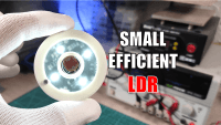
After completing the surface mount assembly, I cleaned the solder flux using a flux removal solvent, then the last assembly part is soldering the LDR to the circuit. The result looks promising, and the LEDs turn on, with the brightness changing based on the light intensity.
I powered the circuit from my 3.7V battery, and the circuit also worked properly. You can notice the LEDs' brightness changing by plugging and unplugging the USB cable due to the power source switching from 3.7V of the battery to 5V of the power adapter. This confirms that our circuit is fully ready to action.
Complete Device Assembly & Test
To complete the gadget, I designed a custom housing and 3D printed it with PLA filament. I considered these 2mm holes on the PCB to screw it to the housing and used 2mm threaded inserts to screw the circuit to the housing. I added a circular plexiglass part to cover the LEDs, and the backside of the device has three holes where I placed small magnets which allow the device to get sticked to metallic surfaces easily. The LEDs' brightness will follow the light intensity, and the device lights on automatically in dark places. You can also plug the USB cable to charge the device when the battery gets low.
In conclusion, this device could help you light the way in dark places and you don't have to worry about the Batteries because it could stay up running at full brightness for around 4 hours when the Battery is fully charged, as soon as the light comes up the LEDs will automatically turns off which saves more power for the dark moments.
Your comments are the most welcomed.
I designed and Assembled this gadget in my home-lab so if you wan to follow the same process then you may need the following tools:
- Digital Microscope Camera LINKMICRO
- Solder Paste CHIPQUIK SMDLTLFP10T5
- Flux removal Solvent
- Hot Plate MHP30
- Solder Iron Weller WE1010NA
- Precision tweezers
The LDR acts as a variable resistor where the measured resistance value depends on the intensity of light applied to its photoconductive material. The lower the light intensity, the higher the resistor value. This interactive component can be used in several applications, and probably the most commonly used purpose of LDR is auto light controlling.
To create the voltage divider circuit for the LDR, I used an NPN transistor and placed the LDR in series with a 10K Ohm resistor at the base of the transistor. This will decrease the voltage at the base by increasing the light intensity, which turns off the transistor and the LEDs. The 10K Ohm series resistor is used to define the circuit light sensitivity. It's important to note that the lowest LDR resistance value is 1K Ohm, so I recommend that the series resistor shouldn’t be lower than 10K Ohm.To power the circuit, I used a 3.7V rechargeable battery, and I included the charging circuit that I made in my previous videos. All I had to do was duplicate the same circuit setup and add a P-MOSFET to help me switch the power from USB to Battery when I disconnect the device from the charging source. This way, the device will automatically switch from being powered by Battery to USB, and I can keep the Battery charging safely.I then transformed the schematic to a PCB design in Altium and set a circular shape for my board. I placed the battery and USB connectors to the edge of the board and set the LEDs around the LDR. You can download the GERBER files of this PCB from this link
Circuit Assembly
After successfully producing and delivering my PCBs from JLCPCB, I set my desktop for assembly and started with depositing solder paste on the exposed pads.
Although I didn't order a stencil to help me with the task, I referred to Altium 365 to avoid any assembly mistakes, especially with all these tiny components. I then placed the parts to the PCB and moved to my hotplate to complete the assembly.
After completing the surface mount assembly, I cleaned the solder flux using a flux removal solvent, then the last assembly part is soldering the LDR to the circuit. The result looks promising, and the LEDs turn on, with the brightness changing based on the light intensity.
I powered the circuit from my 3.7V battery, and the circuit also worked properly. You can notice the LEDs' brightness changing by plugging and unplugging the USB cable due to the power source switching from 3.7V of the battery to 5V of the power adapter. This confirms that our circuit is fully ready to action.
Complete Device Assembly & Test
To complete the gadget, I designed a custom housing and 3D printed it with PLA filament. I considered these 2mm holes on the PCB to screw it to the housing and used 2mm threaded inserts to screw the circuit to the housing. I added a circular plexiglass part to cover the LEDs, and the backside of the device has three holes where I placed small magnets which allow the device to get sticked to metallic surfaces easily. The LEDs' brightness will follow the light intensity, and the device lights on automatically in dark places. You can also plug the USB cable to charge the device when the battery gets low.
In conclusion, this device could help you light the way in dark places and you don't have to worry about the Batteries because it could stay up running at full brightness for around 4 hours when the Battery is fully charged, as soon as the light comes up the LEDs will automatically turns off which saves more power for the dark moments.
Your comments are the most welcomed.
Diskussion (4 Kommentare)