
Sensor Device for Burglary Prevention
The battery-powered device detects movement in front of the window using radar technology and begins to flash visibly through the glass pane, serving as an immediate deterrent for burglars. For windows with thermal coating, impermeable to low-power radar waves, an alternative version was developed, in which the radar sensor is replaced by a twilight sensor.
Burglars tend to favour doors and windows that are not easily visible from public places.
However, what they dislike are clear indications of activities inside the building, especially as a result of person recognition.
The device outlined below detects movements in front of the window using radar technology and begins to flash visibly through the glass pane, serving as an immediate deterrent.
On the other hand, many modern windows feature a thermal coating that is impermeable to low-power radar waves.
For such cases, an alternative version was developed, in which the radar sensor is replaced by a twilight sensor. The device flashes during twilight and at night, typically several times within a minute, indicating that the room is secured.
For a detailed explanation of the device’s design and operation, please refer to the attached document: Burglary Prevention_V1.
- Radar or twilight sensor
- Power management
- Microcontroller
- Charging controller.
The device uses the cheap HW-MS03 “radar sensor” board, which requires a supply current of 4 mA only.
When a nearby object, such as a human body, reflects these waves, the oscillator becomes detuned. This change is then recognized by the onboard PIR motion detector BISS0001.
The minimum supply voltage of 3.7 V requires ─ in combination with a Lion-battery ─ a boost converter.
To ensure the device detects movement only in front of the window ─ rather than within the building ─ all circuit components must be enclosed within a metal housing, featuring only a single aperture.
The twilight sensor is an alternative solution for window panes with thermal coating, which are impermeable to low-power radar waves.
By substituting the radar sensor with a twilight sensor, all other components, including the housing, could remain unchanged.
Although motion detection is no longer available, the deterrent effect of the flashing device during darkness should be just as effective.
The main components of the circuit shown in document: Light Sensor_Circuit diagram are the LDR R4, the current source with JFET Q1, and the micro-power comparator U1.
The day/night sensitivity threshold can be adjusted using potentiometer RV1 as part of the current source.
In view of the current consumption of the radar sensor, a Panasonic Li-Ion battery with 3200 mAh capacity has been selected to ensure an extended operational lifetime without recharging.
The key features of the power management are
- Turn-on / turn-off of the device through pushbutton controller U2 and load switch Q1 saving space
- Continuous battery monitoring to avoid deep discharge with automatic device shut-down if voltage falls below 3.0 V.
- Sequential powering of both the boost converter U4 and microcontroller U9 using a dual load switch U6, maximising battery lifetime.
- Delivery of 3.9 V supply voltage for the radar sensor through boost converter U4.
- Generation of a warning trigger signal for the MCU when battery voltage drops below 3.4 V, indicating the need for recharging.
The MCU U9 (ATtiny85) is powered on only when the radar or twilight sensor generates an active high signal ─ indicating either the presence of a person or darkness, respectively.
Once powered, the controller drives the flashing LED pair D4 via MOSFET Q2, producing short double pulses (standard pattern).
If the battery voltage drops below 3.4 V (detected by the MCU through the BAT34 signal), the flashing pattern changes to single pulses only. This serves as an indicator that the battery needs to be recharged within the next days.
The MCU software varies slightly depending on whether the radar or twilight sensor is used.
In this case, the MCU turns off its own power via the HOLD signal to low.
The device is powered via the USB-C port, receiving 5 Vdc from an external charger.
The battery controller U1 uses CCCV charging mode, which is required for Li-Ion batteries.
LED D1 (red) lights up during the charging process, while LED D2 (green) turns on to indicate that charging is complete.
The temperature is monitored by thermistor RV1 placed adjacent to the battery.
Resistor R5 (1 kΩ) sets the maximum charging current to 1 A.
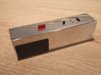
The metal housing should be designed to be as compact as possible to ensure it fits neatly onto the window frame as shown by example on Figure 01.
However, the overall dimensions of the device are largely determined by the use of an 18650 battery.
The mechanical design was refined using FreeCAD, with the resulting model exported as DXF files for CNC milling.
Figure 02 illustrates the 3D model, highlighting the mounting space for both the PCB and battery, as well as the front aperture designed to accommodate either the radar or twilight sensor board.
Figure 03 offers a visual overview of the internal arrangement of the components within the housing.
The top cover contains openings for the flashing LED pair, the ON/OFF microswitch, both charging status LEDs, and the USB-C port.
In the variant with twilight sensor, the aluminium frame features an opening positioned above the sensor aperture. This allows access to the potentiometer RV1 and the measurement points required for adjusting the day/night threshold.
The two largely identical variants are shown on Figure 04.
As illustrated in Figure 05, the battery is directly mounted on the underside of the circuit board using clamps, conserving space within the housing. Components are arranged on both sides of the PCB to maximise the use of available area.
SMD components were installed using hot air reflow. For components with complex footprint, individual stencils and solder paste were employed to achieve precise placement and reliable soldering.
The small twilight sensor board incorporates the components depicted in Figure 06.
For simplification, a single-layer PCB was designed in KiCad, and the resulting DXF file was sent to the CNC mill with engraver.
For the variant equipped with a twilight sensor, the original opaque plastic cover was replaced by semi-transparent material.
In order to prevent short circuits between the battery clamps and the aluminium frame within the installation space, heat shrink tubing was applied to insulate these components effectively.
Want to build a project?
Bring your design to life with the Elektor PCB Service, powered by Eurocircuits. Upload the project files and order professionally manufactured PCBs or assembled boards through a proven European production platform.
Supporting KiCad, Eagle, Gerber, and ODB++ formats, the service is suitable for everything from prototypes and validation builds to series production and volume manufacturing.
Made in Europe. Fast. Reliable. Professional.
Diskussion (4 Kommentare)