
Inverted Pendulum [ 150175-I ]
Description----------------This project is freely inspired from the Cubli project from ETH Zurich.http://www.elektor.fr/news/un-cube-mobile-et-impossible-et-d-placer/
Description
----------------
This project is freely inspired from the Cubli project from ETH Zurich.
http://www.elektor.fr/news/un-cube-mobile-et-impossible-et-d-placer/
http://www.idsc.ethz.ch/Research_DAndrea/Cubli
Being 1D, it is much more simpler that the Cubli but the basic principle remains the same:
It is made of a right-angled triangle prism holding its equilibirum on an edge.
Equilibrium is achieved by the proper regulation of a reaction wheel.
If you ask yourself "what is the purpose of such a thing ?", I would say:
"it's useless, so completely indispensable". It would just be fun to see the pendulum defeating gravity by holding an improbable position and even balancing around it. But it can also be the perfect project for students to study modern control theory.
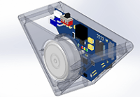
From the begining I wanted the pendulum to be small and completely self-contained (i.e. without requiring a big power supply outside). Therefore the casing can hold a battery and the electronic incorporates the power supply and the motor driver required to drive the motor and its reaction wheel. Nevertheless, everything fit in compact dimensions: triangle edge is 10cm long while depth is about 5cm.
The project is supplemented by a PC Control Station software that is used to calibrate the components, but also to display rich information about the pendulum state.
Project status - February 2015
--------------------------------------------
That's it. The pendulum can jump and hold in equilibrium. I'm proud to show you a video of its performance here:
Of course there is still room for improvement: it still have a few hiccups and I have not implemented a control law to make it swing yet. Anyway the hard part is done.
As mentionned before, the axle of the reaction wheel has been 3D printed, like for the pendulum body. The inertia comes from a metal ring simply plugged arround. No glue, no complex fixation, the whole pendulum is assembled with only 9 screws.
Project status - December 2014
--------------------------------------------
The casing has been modelized with SolidWorks and then 3D printed at sculpteo.com. The result is quiet impressive. I added some photo to show the result of the final assembly.
The reaction wheel is still missing and will be prototyped soon.
Project status - November 2014
--------------------------------------------
- Electronic is prototyped and completely tested. Everything is working as expected.
- Control Station is able to display pendulum state, history, and to send commands.
- Pendulum software is done at 80%. It can collect all the sensors data, send it to the UART, drive the motor. A simple Kalman filter that just estimates body angle is up and running.
- Casing: For now, it is in cardboard :-). Final casing is being modeled.
- Control software is tested under Matlab simulation only.
What is missing:
1) Calibration software must be implemented, both on the CS and on the pendulum
2) A true descent 3D printed casing is needed
3) The reaction wheel must be designed
4) Equilibrium control loop must be implemented in the pendulum
Components
-----------------
The motor driving the reaction wheel is a Brush Less DC motor that can deliver a torque of 50mNm under a current of 2A. The reaction wheel is directly coupled to the motor axis.
The battery is a 7,4V Lipo 2S 30C 450mah from Team Orion. It can deliver up to 13A and its weight is only 30g.
The casing is still under investigation. I'm currently thinking to a simple 3D printed one.
The reaction wheel construction is still under investigation
Total wheight of the motor (75g), battery (30g), electronic (30g) and casing (~40g) should be around 180g.
Electronic
-------------
The main part of the PCB is dedicated to a 12@2A SMPS supplying a Brusless DC motor driver. The BLDC driver is built around a L6235 IC. It is quite compact and can be easily driven by a µc through several simple I/O. Most importantly, it is driven by being given a current reference. Current is an image of the torque on a BLDC motor and torque is the parameter controlled by the regulation. In addition, the BLDC driver outputs the motor speed that is decoded from the motor hall sensors.
The IMU is made of a 3 axis accelerometer (ADXL345) and a 1 axis gyro (ISZ2510). There are used to sense gravity and body angular rotation.
The µc is a Microchip dsPIC. It is aimed at collecting the sensors data, input them in the regulation loop, compute the regulation torque and control the BLDC accordingly. It can also ouput the pendulum telemetries through an UART port.
Regulation
----------
Regulation loop has first been simulated with Matlab. The Matlab sripts simulate all the physics of the pendulum, its sensors and the motor. Because the pendulum is a Single Input Multiple Output (SIMO) system, it is better driven with a state feedback LQR control loop. Because LQR assume pendulum full state knowledge, an additional Kalman filter is needed to estimate the state of the pendulum through its sensors.
Matlab simulations show good results to maintain equilibrium even when facing external perturbations. However it is not still implemented in the real pendulum.
Control Station
--------------------
The Control Station is a Windows application written in C#. It is aimed at sending commands to the pendulum for calibration purpose, and also to collect and log the telemetries received when pendulum is running.
Want to build a project?
Bring your design to life with the Elektor PCB Service, powered by Eurocircuits. Upload the project files and order professionally manufactured PCBs or assembled boards through a proven European production platform.
Supporting KiCad, Eagle, Gerber, and ODB++ formats, the service is suitable for everything from prototypes and validation builds to series production and volume manufacturing.
Made in Europe. Fast. Reliable. Professional.
Diskussion (6 Kommentare)