
I finally found a useful application for dekatrons!
Dekatrons are gas filled counting tubes dating from the fifties. For a short period in history, they were used as counters and memory cells in computers (Harwell Witch computer ). Each tube could hold one digit from 1 to 10, so you needed a lot of tubes to build a computer!
I had a couple of those tubes lying around and I was thinking about a project in which they could be put into new use. Sometimes people who build nixie clocks add one dekatron as a seconds counter, which is nice, but I wanted something new.
In this article I am presenting the 7-band stereo audio spectrum analyser with dekatron output. This is a great addition for any audiophile with a tube amplifier who wants to augment to the visual spectacle!
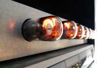
The idea is simply this: instead of representing the audio spectrum with a bar graph, using LED displays – or even more boring – an LCD, the volume of the audio signal in each frequency band is indicated by a number of dots lighting up in one of the dekatrons. Each dekatron forms a circle of 30 dots. The left 15 dots represent the left part of the stereo signal and the right 15 dots the right signal.
The microcontroller is an ATMEGA328, well known from the Arduino. It’s not used as an Arduino though. The small (300 line) program is written in C using Atmel Studio.
As spectrum analyser, a dedicated MSGEQ7 chip from the American company Mixed Signals is used, that analyses the audio signal and divides it into 7 frequency bands. The seven levels can then be obtained by a microcontroller by sending digital commands to the chip. The chip responds with an analog signal on its output, which is converted by the A/D converter in the microcontroller. There are two of those chips in this design, one for each audio channel.
Side note: the spectrum analyser ic MSGEQ7
Where to buy: NOT on Ebay and NOT on Aliexpress – beware of fake chips. I bought some chips from one seller on Aliexpress and from one seller on Ebay and they both came up with a fake chip with date code 1902. See fig. 5 The red dot on the fake chip is from me. I bought the chip on the left from Sparkfun for $4.95.
It easy to determine if you have a genuine or fake chip. Just connect 5V between pin 1 (VDD=+5V) and pin 2 (VSS=0V) and measure the current. A genuine chip uses less than 1mA. The fake ones I had consumed more than 10mA..
Link to Youtube video: https://youtu.be/ol-LANzmlDs
Getting rid of noise in the MSGEQ7 audio spectrum analyzer ic.
This chip was already covered in the May 2019 issue of Elektor, but what they didn't tell you is how to handle noise issues with that chip.
My first attempts in using the chip were not successful because of noise. One in approximately every ten values from the chip was just way off. In forums on the internet, you can see that other people struggle with the same problem. I have taken a number of measures to overcome this:
Dekatron Unit
The controller communicates with the dekatron units using three wire serial communication at 5Mb/s, also known as SPI. Each dekatron sits on a unit including a 74HC595 and a number of MPSA42 transistors, which do the high voltage stuff. The design gives room for 8 MPSA42’s, but the 6802 dekatron I used only needs 7 of those.
I designed a pcb size 4cm×4.5cm for this unit, or actually two pcb’s because the unit consists of two pcb’s stacked on top of each other. The top pcb contains the dekatron socket the anode resistor, while the bottom resistor contains all the rest. The holes for the dekatron’s socket are suitable for different types of sockets (both ceramic and metal/plastic). The bottom pcb has a male connector SV1 on the left and a female connector SV2 on the right, so they can easily be daisy chained into a string of arbitrary length.
In order to cut on pcb manufacturing cost, both pcb’s are panelized onto one and two of those are panelized again into a pcb of size 8cm × 9cm. Pcb manufactures often offer a prototyping service yielding 10 pcb’s for little money, so you end up with pcb’s for 20 units at a bargain.
Side note: High voltage warningDekatrons run on voltages as high as 450V. If you are not comfortable in working with high voltages, don’t attempt to build this project or work with these tubes at all. Even after turning off the mains supply, there can still be a high voltage present on the high voltage capacitor. Before working on the circuit, make sure the capacitor is discharged.
Power SupplyThe design has two power supplies: a 5V and a 400V power supply. The 5 volt supply is straightforward: a 9V transformer, a diode bridge, a 78L05 and some capacitors.
In the dekatrons a gas discharge takes place. In order for this discharge to ignite, a relatively high VPP voltage of approximately 400V is needed. My first solution was a switching supply built around a MC34063 or even a simple 555. But I found out such a supply causes a lot of interference with the analogue signals (especially on the output of the MSGEQ7) and it turned out near to impossible to get good results. Then I found a supplier who makes transformers according to customer specifications in China, Yollen Electrical Store. https://www.aliexpress.com/store/5652013
I ordered a couple of small 350V, 1VA, 50Hz transformers from him for €3 each plus €6,50 shipping. Add four 1N4007 diodes, a capacitor 10µF 500V and that is all you need.
Despite the fact that this design uses tubes, the power consumption is very low. Dekatrons are so called cold cathode devices, so there is no heater! The only power that each tube draws is 0.3mA anode current which adds up to approximately 1W power on the high voltage side. Both transformers are rated 1VA and the total power consumption is below 2W.
SoftwareThe software for the ATMEGA328 is written in C in AtmelStudio. The work is either done in the main loop or in interrupt service routines. Interfacing with the analyser chip, including control of the ADC is done from the main loop. Interfacing with the dekatron units, using SPI is done from interrupt routines.
The left and right audio signals are fed to two analyser chips. Each of these contains 7 band pass filters (60Hz, 150Hz etc.) and the signal level is sampled. The AVR gets the audio levels as analog signals, digitizes them and uses the dekatrons as display devices.
In order to reduce noise at the software level, each value is measured 15 times and the best values out of these measurements are taken. As there are 7 frequency bands and 2 channels (L and R), 210 analog to digital conversions are done each cycle, before the display is changed!
This works in detail as follows. Both analyser chips MSGEQ7 are reset. A strobe pulse is given to both chips. Now the level of the first frequency band is output on pin 3 of the chips. An analogue to digital conversion (ADC) takes place for the left channel. An ADC takes place for the right channel. Both ADC’s are repeated and repeated again. Now there are three values for left and three values for right. The lowest and the highest values are thrown away, only the middle values are kept.
A strobe pulse is given to both chips. Now the second frequency band is treated in the same way. The third up to the seventh band are also treated the same way.
Everything that is described up to here is repeated 5 times and the average values are used.
Controlling the dekatrons work as follows. In the view of this program, each dekatron has 60 states. Why 60, isn't a dekatron supposed to have 10 states, hence 'deka'? Yes originally, the dekatron is supposed to have ten stable states. But in between each two stable states are two transitional states. In total, the dekatron has 30 cathodes, 10 for each stable state and between each stable state there are two cathodes for the transition. Originally the dekatron was used as a counting tube. By applying a shifted pulse on the first and then then the second transitional cathode, it could count "one up". This also means that, with a dekatron, it is easy to move the dot from one position to an adjacent position. But it is not so easy (and most of the time not even possible) to move the dot directly from one position to a random other position. This is only possible for a few of the stable positions. For some dekatrons, all 10 stable positions have “random access”, but other dekatrons have fewer. The 6802 that I used only positions 0, 5, 8 and 9 have their pins exposed on the socket. In this design, the 0 position is initially used as a starting point and thereafter, the dot only moves to adjacent positions, either one step to the left or one step to the right.
In this application, we use all 30 cathodes. Furthermore, there is the possibility to energize two cathodes (lying next to each other) at the same time and this is used as transition between one cathode and the next. In this way we arrive at 60 states.
This application relies on rapid switching between states. So rapid that it can fool the eye. The current state of dekatron i (a number between 0 and 59) is stored in values[i]. Like a windscreen wiper, this is rapidly varied between two extreme states. The extreme states are stored in minima[i] and maxima[i]. The current direction of movement (towards minima or towards maxima) is stored in the Boolean orient[]. The state is changed every 150us. When 150us have passed, interrupt service routine TIMER0_COMPA_vect() is called. At this time, the new values to be sent out to the dekatrons are already prepared in buffer[]. The first value out of buffer[] is sent out over the SPI bus at a rate of 5Mb/s. When this SPI transfer is finished, interrupt service routine SPI_STC_vect() is called, which sends out the next byte over the SPI bus. When all 7 bytes are sent out in this way, SPI_STC_vect() calculates the new values[]. The value of buffer[] is calculated, it must contain the actual bit pattern to be sent to the SPI bus. The map[] array contains the translation from values[i] to buffer[i]. If necessary (when values[i] equals minima[i] or maxima[i]), the orient[i] is also inverted.
Example. For dekatron #3, the values are as follows:
value[3]=10 buffer[3]=2 (this is the bit pattern that corresponds to state 10) minima[3]=2 maxima[3]=11 orient[3]=1 (move to the right, towards 11)
Because orient[3] is 1, we must move to the right, so value[s] must become 11. Therefore the new values are:
value[3]=11 buffer[3]=6 (this is the bit pattern that corresponds to state 11) minima[3]=2 maxima[3]=11 orient[3]=1 (move to the right, towards 11)
In the next cycle, value[3] has become equal to maxima[3], the orientation must change to "left" and the new values are:
value[3]=11 buffer[3]=6 (this is the bit pattern that corresponds to state 11) minima[3]=2 maxima[3]=11 orient[3]=0 (move to the right, towards 2) In the next cycle the values will be: value[3]=10 buffer[3]=2 (this is the bit pattern that corresponds to state 10) minima[3]=2 maxima[3]=11 orient[3]=0 (move to the right, towards 2)
Be aware that a dekatron is a circular thing and the state model is also circular. You would maybe expect that for each dekatron i, minima[i] should always be numerically lower than maxima[i], but in a circular model, this is not required. Values like the following are perfectly valid:
value[3]=0 buffer[3]=64 (this is the bit pattern that corresponds to state 0) minima[3]=58 maxima[3]=2 orient[3]=1 (move to the left, towards 58)
In the next cycle, the values would be:
value[3]=59 buffer[3]=66 (this is the bit pattern that corresponds to state 59) minima[3]=58 maxima[3]=2 orient[3]=1 (move to the left, towards 58)
The main loop is in charge of changing the values of minima[] and maxima[] according to the sampled analogue values. The interrupt service routines will handle the rest. However there is one catch. Normally, values[i] is supposed to lie between minima[i] and maxima[i][1]. If this is no longer the case, values[i] must return to the range between minima[i] and maxima[i] a.s.a.p! This is not done abruptly but step by step and the function that is in charge is checkRange(). It checks whether this condition is the case. If that is so, the only thing it will do is change the value of orient[i] and only if that helps to move within bounds asap.
[1] this is easier said than it really is, because in a circular model values[i] is always "between" minima[i] and maxima[i]. We also have to take orient[i] into account. If orient[i]==0, we are moving to the right and values[i] should arrive at maxima[i] before arriving at minima[i]. If this is not the case, values is no longer "between" minima[i] and maxima[i]. Similar when orient[i]==1.
Mechanical build
There were essentially two options: like a tube amplifier, put the tubes vertical in the style of the figure to the left (fig. 13). Or put the tubes horizontal. I chose for the latter, because the tubes must be looked upon from the top. I wanted a housing for the project that could be placed in a stack of audio equipment. So I took the metal housing of an old piece of equipment (a cable tv decoder). I used it back to front and I added a new front panel, which is a piece of sheet metal taken from an old pc, with holes precisely drilled with a so called step bit as in figure below. Never drill a hole in sheet metal with a normal drill because it will not become round but more or less triangular! The holes were carefully predrilled with a 3018 CNC router (figure below), which I normally use for pcb milling. I attached the front panel to the housing using small magnets (fig. 14).
The transformers and the pcb’s were mounted on a piece of plastic household cutting board, which was in turn attached to the housing. The dekatron units were all together screwed on a sturdy metal bar which was also attached to the housing. For safety, I connected the metal housing to earth.
Possible modifications It is possible to simplify the design by making a mono model (saves you one MSGEQ7) or to reduce the number of frequency bands. E.g. merge the 7 bands into 5 bands by combining the two highest and the two lowest bands. It is also possible to use other dekatrons than the 6802, there are no particular features of the 6802 that make it more suitable than any other dekatron.
I'm currently working on a nice aluminium front, because the piece of old sheet metal is a bit...rough.
In this article I am presenting the 7-band stereo audio spectrum analyser with dekatron output. This is a great addition for any audiophile with a tube amplifier who wants to augment to the visual spectacle!
The idea is simply this: instead of representing the audio spectrum with a bar graph, using LED displays – or even more boring – an LCD, the volume of the audio signal in each frequency band is indicated by a number of dots lighting up in one of the dekatrons. Each dekatron forms a circle of 30 dots. The left 15 dots represent the left part of the stereo signal and the right 15 dots the right signal.
The microcontroller is an ATMEGA328, well known from the Arduino. It’s not used as an Arduino though. The small (300 line) program is written in C using Atmel Studio.
As spectrum analyser, a dedicated MSGEQ7 chip from the American company Mixed Signals is used, that analyses the audio signal and divides it into 7 frequency bands. The seven levels can then be obtained by a microcontroller by sending digital commands to the chip. The chip responds with an analog signal on its output, which is converted by the A/D converter in the microcontroller. There are two of those chips in this design, one for each audio channel.
Side note: the spectrum analyser ic MSGEQ7
Where to buy: NOT on Ebay and NOT on Aliexpress – beware of fake chips. I bought some chips from one seller on Aliexpress and from one seller on Ebay and they both came up with a fake chip with date code 1902. See fig. 5 The red dot on the fake chip is from me. I bought the chip on the left from Sparkfun for $4.95.
It easy to determine if you have a genuine or fake chip. Just connect 5V between pin 1 (VDD=+5V) and pin 2 (VSS=0V) and measure the current. A genuine chip uses less than 1mA. The fake ones I had consumed more than 10mA..
Link to Youtube video: https://youtu.be/ol-LANzmlDs
Getting rid of noise in the MSGEQ7 audio spectrum analyzer ic.
This chip was already covered in the May 2019 issue of Elektor, but what they didn't tell you is how to handle noise issues with that chip.
My first attempts in using the chip were not successful because of noise. One in approximately every ten values from the chip was just way off. In forums on the internet, you can see that other people struggle with the same problem. I have taken a number of measures to overcome this:
- Software: sampling the same value multiple times and get multiple measurements from the chip.
- Throw away highest and lowest values and average the rest
- Hardware: avoid the switching power supply.
- Physical distance: didn’t really help.
- Separate power supplies. Tried that. Didn’t help.
- RC filter in the digital path of the STROBE signal! This helped a lot.
Dekatron Unit
The controller communicates with the dekatron units using three wire serial communication at 5Mb/s, also known as SPI. Each dekatron sits on a unit including a 74HC595 and a number of MPSA42 transistors, which do the high voltage stuff. The design gives room for 8 MPSA42’s, but the 6802 dekatron I used only needs 7 of those.
I designed a pcb size 4cm×4.5cm for this unit, or actually two pcb’s because the unit consists of two pcb’s stacked on top of each other. The top pcb contains the dekatron socket the anode resistor, while the bottom resistor contains all the rest. The holes for the dekatron’s socket are suitable for different types of sockets (both ceramic and metal/plastic). The bottom pcb has a male connector SV1 on the left and a female connector SV2 on the right, so they can easily be daisy chained into a string of arbitrary length.
In order to cut on pcb manufacturing cost, both pcb’s are panelized onto one and two of those are panelized again into a pcb of size 8cm × 9cm. Pcb manufactures often offer a prototyping service yielding 10 pcb’s for little money, so you end up with pcb’s for 20 units at a bargain.
Side note: High voltage warningDekatrons run on voltages as high as 450V. If you are not comfortable in working with high voltages, don’t attempt to build this project or work with these tubes at all. Even after turning off the mains supply, there can still be a high voltage present on the high voltage capacitor. Before working on the circuit, make sure the capacitor is discharged.
Power SupplyThe design has two power supplies: a 5V and a 400V power supply. The 5 volt supply is straightforward: a 9V transformer, a diode bridge, a 78L05 and some capacitors.
In the dekatrons a gas discharge takes place. In order for this discharge to ignite, a relatively high VPP voltage of approximately 400V is needed. My first solution was a switching supply built around a MC34063 or even a simple 555. But I found out such a supply causes a lot of interference with the analogue signals (especially on the output of the MSGEQ7) and it turned out near to impossible to get good results. Then I found a supplier who makes transformers according to customer specifications in China, Yollen Electrical Store. https://www.aliexpress.com/store/5652013
I ordered a couple of small 350V, 1VA, 50Hz transformers from him for €3 each plus €6,50 shipping. Add four 1N4007 diodes, a capacitor 10µF 500V and that is all you need.
Despite the fact that this design uses tubes, the power consumption is very low. Dekatrons are so called cold cathode devices, so there is no heater! The only power that each tube draws is 0.3mA anode current which adds up to approximately 1W power on the high voltage side. Both transformers are rated 1VA and the total power consumption is below 2W.
SoftwareThe software for the ATMEGA328 is written in C in AtmelStudio. The work is either done in the main loop or in interrupt service routines. Interfacing with the analyser chip, including control of the ADC is done from the main loop. Interfacing with the dekatron units, using SPI is done from interrupt routines.
The left and right audio signals are fed to two analyser chips. Each of these contains 7 band pass filters (60Hz, 150Hz etc.) and the signal level is sampled. The AVR gets the audio levels as analog signals, digitizes them and uses the dekatrons as display devices.
In order to reduce noise at the software level, each value is measured 15 times and the best values out of these measurements are taken. As there are 7 frequency bands and 2 channels (L and R), 210 analog to digital conversions are done each cycle, before the display is changed!
This works in detail as follows. Both analyser chips MSGEQ7 are reset. A strobe pulse is given to both chips. Now the level of the first frequency band is output on pin 3 of the chips. An analogue to digital conversion (ADC) takes place for the left channel. An ADC takes place for the right channel. Both ADC’s are repeated and repeated again. Now there are three values for left and three values for right. The lowest and the highest values are thrown away, only the middle values are kept.
A strobe pulse is given to both chips. Now the second frequency band is treated in the same way. The third up to the seventh band are also treated the same way.
Everything that is described up to here is repeated 5 times and the average values are used.
Controlling the dekatrons work as follows. In the view of this program, each dekatron has 60 states. Why 60, isn't a dekatron supposed to have 10 states, hence 'deka'? Yes originally, the dekatron is supposed to have ten stable states. But in between each two stable states are two transitional states. In total, the dekatron has 30 cathodes, 10 for each stable state and between each stable state there are two cathodes for the transition. Originally the dekatron was used as a counting tube. By applying a shifted pulse on the first and then then the second transitional cathode, it could count "one up". This also means that, with a dekatron, it is easy to move the dot from one position to an adjacent position. But it is not so easy (and most of the time not even possible) to move the dot directly from one position to a random other position. This is only possible for a few of the stable positions. For some dekatrons, all 10 stable positions have “random access”, but other dekatrons have fewer. The 6802 that I used only positions 0, 5, 8 and 9 have their pins exposed on the socket. In this design, the 0 position is initially used as a starting point and thereafter, the dot only moves to adjacent positions, either one step to the left or one step to the right.
In this application, we use all 30 cathodes. Furthermore, there is the possibility to energize two cathodes (lying next to each other) at the same time and this is used as transition between one cathode and the next. In this way we arrive at 60 states.
This application relies on rapid switching between states. So rapid that it can fool the eye. The current state of dekatron i (a number between 0 and 59) is stored in values[i]. Like a windscreen wiper, this is rapidly varied between two extreme states. The extreme states are stored in minima[i] and maxima[i]. The current direction of movement (towards minima or towards maxima) is stored in the Boolean orient[]. The state is changed every 150us. When 150us have passed, interrupt service routine TIMER0_COMPA_vect() is called. At this time, the new values to be sent out to the dekatrons are already prepared in buffer[]. The first value out of buffer[] is sent out over the SPI bus at a rate of 5Mb/s. When this SPI transfer is finished, interrupt service routine SPI_STC_vect() is called, which sends out the next byte over the SPI bus. When all 7 bytes are sent out in this way, SPI_STC_vect() calculates the new values[]. The value of buffer[] is calculated, it must contain the actual bit pattern to be sent to the SPI bus. The map[] array contains the translation from values[i] to buffer[i]. If necessary (when values[i] equals minima[i] or maxima[i]), the orient[i] is also inverted.
Example. For dekatron #3, the values are as follows:
value[3]=10 buffer[3]=2 (this is the bit pattern that corresponds to state 10) minima[3]=2 maxima[3]=11 orient[3]=1 (move to the right, towards 11)
Because orient[3] is 1, we must move to the right, so value[s] must become 11. Therefore the new values are:
value[3]=11 buffer[3]=6 (this is the bit pattern that corresponds to state 11) minima[3]=2 maxima[3]=11 orient[3]=1 (move to the right, towards 11)
In the next cycle, value[3] has become equal to maxima[3], the orientation must change to "left" and the new values are:
value[3]=11 buffer[3]=6 (this is the bit pattern that corresponds to state 11) minima[3]=2 maxima[3]=11 orient[3]=0 (move to the right, towards 2) In the next cycle the values will be: value[3]=10 buffer[3]=2 (this is the bit pattern that corresponds to state 10) minima[3]=2 maxima[3]=11 orient[3]=0 (move to the right, towards 2)
Be aware that a dekatron is a circular thing and the state model is also circular. You would maybe expect that for each dekatron i, minima[i] should always be numerically lower than maxima[i], but in a circular model, this is not required. Values like the following are perfectly valid:
value[3]=0 buffer[3]=64 (this is the bit pattern that corresponds to state 0) minima[3]=58 maxima[3]=2 orient[3]=1 (move to the left, towards 58)
In the next cycle, the values would be:
value[3]=59 buffer[3]=66 (this is the bit pattern that corresponds to state 59) minima[3]=58 maxima[3]=2 orient[3]=1 (move to the left, towards 58)
The main loop is in charge of changing the values of minima[] and maxima[] according to the sampled analogue values. The interrupt service routines will handle the rest. However there is one catch. Normally, values[i] is supposed to lie between minima[i] and maxima[i][1]. If this is no longer the case, values[i] must return to the range between minima[i] and maxima[i] a.s.a.p! This is not done abruptly but step by step and the function that is in charge is checkRange(). It checks whether this condition is the case. If that is so, the only thing it will do is change the value of orient[i] and only if that helps to move within bounds asap.
[1] this is easier said than it really is, because in a circular model values[i] is always "between" minima[i] and maxima[i]. We also have to take orient[i] into account. If orient[i]==0, we are moving to the right and values[i] should arrive at maxima[i] before arriving at minima[i]. If this is not the case, values is no longer "between" minima[i] and maxima[i]. Similar when orient[i]==1.
Mechanical build
There were essentially two options: like a tube amplifier, put the tubes vertical in the style of the figure to the left (fig. 13). Or put the tubes horizontal. I chose for the latter, because the tubes must be looked upon from the top. I wanted a housing for the project that could be placed in a stack of audio equipment. So I took the metal housing of an old piece of equipment (a cable tv decoder). I used it back to front and I added a new front panel, which is a piece of sheet metal taken from an old pc, with holes precisely drilled with a so called step bit as in figure below. Never drill a hole in sheet metal with a normal drill because it will not become round but more or less triangular! The holes were carefully predrilled with a 3018 CNC router (figure below), which I normally use for pcb milling. I attached the front panel to the housing using small magnets (fig. 14).
The transformers and the pcb’s were mounted on a piece of plastic household cutting board, which was in turn attached to the housing. The dekatron units were all together screwed on a sturdy metal bar which was also attached to the housing. For safety, I connected the metal housing to earth.
Possible modifications It is possible to simplify the design by making a mono model (saves you one MSGEQ7) or to reduce the number of frequency bands. E.g. merge the 7 bands into 5 bands by combining the two highest and the two lowest bands. It is also possible to use other dekatrons than the 6802, there are no particular features of the 6802 that make it more suitable than any other dekatron.
I'm currently working on a nice aluminium front, because the piece of old sheet metal is a bit...rough.
Want to build a project?
Bring your design to life with the Elektor PCB Service, powered by Eurocircuits. Upload the project files and order professionally manufactured PCBs or assembled boards through a proven European production platform.
Supporting KiCad, Eagle, Gerber, and ODB++ formats, the service is suitable for everything from prototypes and validation builds to series production and volume manufacturing.
Made in Europe. Fast. Reliable. Professional.
Updates des Autors