
ESP32 Portable GPS Data-logger/Weather Station
A portable GPS data-logger built for travel, with the added bonus of acting as a weather station with MQTT sensor while sitting on my shelf!
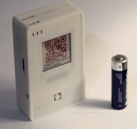
This is a finished prototype built for the purpose of logging GPS information while traveling.
The system uses only simple to use modules with excellent documentations that anyone should be able to reproduce even on a breadboard. The ESP32 is used due to it's vast number of I/Os needed for all the components as well as it's WiFi capabilities
Bill of materials and costs and rough cost
- ESP32 WROOM module ($4)
- u-Blox M8N GPS module (OR similar) ($10)
- Tricolor (B/W/R) 1.54in E-paper ($20)
- BME280 temperature/humidity/pressure sensor ($4)
- SD Card module ($1)
- TP4056 Li-Po Charging Module ($1)
- Li-Po Battery ($10)
- MISC buttons/switches/passives ($2)
All the features
Current Features (GPS mode)
- GPS logging at programmable intervals (every 20, 30, 60, 300 seconds)
- Programmable dynamic platform mode (u-Blox GPS feature, i.e at sea, or flying)
- Environmental data collection via BME280.
- Astronomical almanac calculation via GPS data
- Datalogged to SD card
- 2.5 days continous run-time on a single charge (4000mAh battery)
Additional Features (Weather Station mode, GPS off)
- Current weather and 3 day forecast via wunderground API
- Sending BME280 sensor data to MQTT server and node-red (If on home wifi)
- Connect to foreign wifi and show weather and forecast at previous GPS location (Work in progress)
Additional Features (Data management modes)
- Ability to view or download stored data file using computer or phone
- Viewing previously collected data in graphs (Work in progress)
Software:
The code is written in Arduino IDE (See github link), it’s not pretty, but it works =D, and that’s all that matters. I'm in the process of declutering the code, theres enough comments to help guide you through, feel free to suggest fixes to my code on github
Hardware:
PCB is designed on KiCAD, I will release the new PCB design at a later day due to a few bugs that requires fixing. It’s a copy/paste of the wiring I’ve done with a working prototype, with minor changes made to a few pin assignments to make routing easier
Diskussion (2 Kommentare)