A camera gimbal that uses the STM32N6570-DK with a pose estimation model to track you and be your cameraman.
Introduction
I've always been fascinated by cinema and the art of camera work. I dream of making a documentary one day, but during my explorations I always came across the same problem - I cannot be simultaneously behind the camera and in front of it. Cinematic tracking shots - my favorite type - require another skilled person behind the camera to rotate, pan, and tilt it. Yet, after my previous contest idea released the magic smoke and could not be replaced in time, I decided to work towards this dream. Thus, I built the EasyGimbal - a camera gimbal that uses the pose estimation capabilities of the STM32N6570-DK development board with its included camera to get me one step closer to that dream. This camera puts you in the center of attention by following you around the frame, horizontally and vertically, while also having the ability to react to your hand gestures.
Project log
Beginning
Initially, I had many different ideas on how to organise the mechanics of the project. However, I decided to go with a relatively conventional and simple organisation using off-the-shelf common parts so that anyone with basic electronics parts that you could find in an Arduino starter kit and a 3D printer could build it.
Mechanics
I wanted to use this project as an opportunity to learn more about practical mechanical design, so I tried to use and model gears in Solidworks which I would then 3D print and test later. I decided to go with a common 5V stepper motor (28BYJ-48) for the yaw axis (horizontal) and a common 5V servo motor (9G servo) for the pitch axis (vertical). The stepper motor would allow for a precise, full 360 degree rotation with a shaft suitable for holding simple gears, while the stepper motor in the pitch axis would allow for finer control over a relatively fixed range of motion.
I wanted to use a new technique I learned about for connecting the separate prototype parts together - plastic welding. Thus, all of the parts were designed to be separate, self-contained, and easily connectable. Plastic welding works well if you have a soldering iron with a presettable temperature. However, a hot glue gun works equally well in my testing. Additionally, as a base to hold all of the components, I used a couple of PLA phone cases I had printed for a previous project. However, you can use any flat piece of PLA or even something like wood.
The mechanics were created bottom-up. The most difficult part was learning how to design with gears, but it turned out to be a very rewarding part of the project. Experimenting with gears in practice for a real project filled in many of the questions I had in my mind from my university classes. I measured the stepper shaft with my calipers and then used Solidworks’ Toolbox to build two gears - one for the stepper’s shaft and another for the main shaft on which the assembly would be placed. The main shaft was a simple cylinder inspired by tank turrets, with the camera assembly and the gear on its bottom acting as the turret. The specific gear settings for the stepper were “Spur gear 1M 12T 20PA 4FW” and “Spur gear 1M 12T 20PA 4FW” for the main shaft.
I experimented with a couple of less successful mechanical designs and ended up with a rather conventional final design. The main principle behind this design was the idea that by changing the servo shaft’s dimensions and orientation, you could also fit a smartphone on it.
Motor isolation board
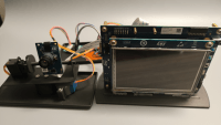
As the used development board is very complex and expensive, I built a motor isolator board so that any electrical failure on the motor side would not damage the development board. The isolation board is a very conventional optocoupler setup that optically isolates the sensitive digital electronics from the noisy and powerful motors. As my initial project had an accident that resulted in a lot of damaged parts, I wanted to avoid any risk to the development board.
I built the motor isolation board from parts I had laying around that I consider to be very common. I also wanted to practice my connector crimping, so I manually crimped all of the required DuPont connectors. The Arduino connector on the back of the development board proved to be very useful for keeping the wiring tidy.
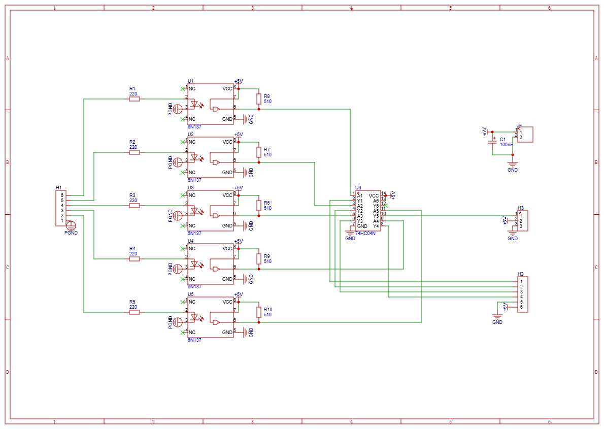
The following schematic is what I came up with and worked perfectly (note the two different grounds - that is for isolation): Firmware
I struggled initially with setting up the toolchain, as the board is staggeringly complex. However, once I had set up the toolchain, I found it quite pleasant to work with. STM32CubeIDE has lots of useful features for every part of the project and I found building new revisions to be easy. Initially, I wanted to start from a blank project, but as I met the complexity of all of the parts needed to get the inference running, I decided to base my project off the official STM32N6-GettingStarted-PoseEstimation example. I’m very grateful that ST offers so many examples with precompiled models. I simply followed the given documentation, which got me running immediately after I installed the prerequisites.
For my app’s required functionality, I built on top of the example. Coincidentally, the example had been using the exact MoveNet pose estimation model I wanted to use, so no additional steps were necessary here. I added four large separate sections to implement my needed functionality:
Camera_tracking.c
Gesture_recognition.c
Joint_list_display.c
Motor_control.c
The camera tracking code takes the raw MoveNet outputs and converts them into useful code structure and landmarks for determining the position and state of the person tracked by the camera. The gesture recognition and joint list use this information to further construct detailed states needed for the motor control. Finally, the motor control follows a list of rules using preset motor constants and PID control to ensure that the subject is being tracked smoothly. The code implements dead zones for the subject where the camera stops. This is done to ensure that the camera is not moving each time the subject moves slightly, which is very distracting. Additionally, this is the way that professional camera operators track subjects. The motor control code uses timers to avoid interfering with the main inference loop. The entire code is well-documented and avoids using magic numbers, so all of the constants are easy to edit, and it is easy to implement new functionality. For creating new files outside of STM32CubeIDE, I wrote a documentation file (“adding_new_c_code_procedure.md”), which I included with the final package.
Build it yourself
Requirements
For the mechanical parts, you will need:
2 or 6 M2 screws with nuts (4 if using MB1854B camera, 8 if using Raspberry Pi Camera)
5 M3 screws with nuts (optionally use 2 heat-insert M3 nuts for the stepper motor holders)
3D printer with ~75g of PLA filament
Soldering iron with presettable temperature or hot glue gun
For the electrical parts, you will need:
STM32N6570-DK development board with MB1854B camera
9 or 17 DuPont wires (9 male-male without isolator PCB, 17 male-female with isolator PCB)
Isolator PCB (optional)
17 male pin headers
5 6N137 or comparable optoisolators
1 74HC04 or 74HC14 hex inverter (any one of the 74x04 and 74x14 will work)
5 220 ohm resistors
5 510 ohm resistors
1 100uF (or comparable) capacitor
A perfboard with suitable numbers of component leads or small wires to connect the parts together
1 28BYJ-48 stepper motor (with included driver board)
1 9G servo motor
Mechanical assembly
Extract the zip file containing all of the STL files and print out all of the components once, except for the stepper pillars, which you should print twice. If you have M3 heat-inserts, insert them now with your presettable temperature soldering iron set at ~220C. Start attaching the components in the following order:
First, start by screwing in the stepper motor in the pillars. The pillars will transmit the forces of the stepper motor to the base. Attach the pillars to the base by plastic welding or gluing them. Then, place the stepper gear on the shaft of the stepper motor. Now, with reference to the stepper gear, place the pedestal gear interface inside of the pedestal shaft. Place the shaft with the gear interface inside such that the teeth of the gears of the interface and the stepper gear match. Then, attach the shaft to the base such that the interface still maintains good contact. Then, remove the pedestal gear interface from the shaft.
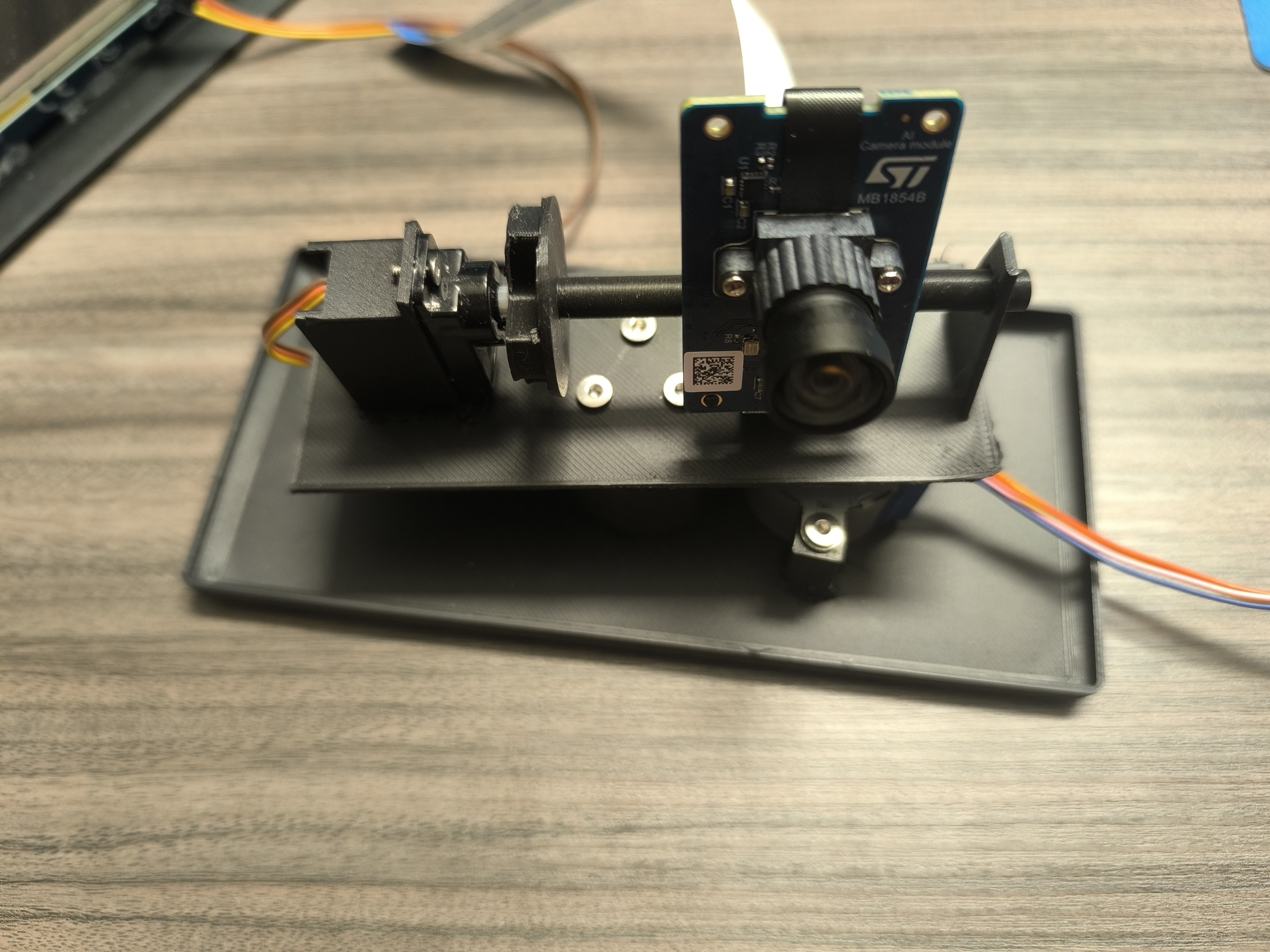
Now, move on to the servo holder. Put the servo in the servo holder with the thicker part on the opposite side from the shaft and screw it in. Put the shaft on the servo and then slide it forward so that it goes into the adapter on the other side of the main pedestal. Once it’s loosely in and sticks out a few mm from the other side, attach the servo holder to the pedestal. Then, simply attach the camera to the servo shaft if using a Raspberry Pi camera, or attach the small MB1854B camera adapter to the bottom of the camera holder and slide the MB1854B on top of it. Finally, screw the finished pedestal to the pedestal gear interface and slide it into the pedestal shaft.
The pedestal for the display is optional, but very practical to have, as it can hold the development board vertically, which is useful while experimenting with the camera in use.
You can use this photo as reference on what the final result should look like:
Motor isolation board
According to the schematic, build the board on a breadboard, perfboard, or even your own PCB. The first two methods are tested and work. If you decide to use the motor isolation board, make sure to use separate power supplies for the development board and the motors, or else the isolation will not be effective. Directly connecting the servo and the stepper control board’s inputs to the STM32N6’s outputs also works. Make sure that you’re using the stepper control board, since the STM32N6 cannot source the required current and you may damage it. Use the following photo as the build reference:
Firmware
For the firmware, extract the zip file containing the firmware and open the .project file with STM32CubeIDE. Simply connect the board in development mode, follow the instructions in the official documentation, then click Run in STM32CubeIDE. If this doesn’t work, run the instructions for manually uploading code in the documentation.
To edit the firmware, start with the main.c file and continue with the gesture_recognition, camera_tracking, and joint_list_display files. To affect the movement of the motor, edit the motor_control files. Constants like the confidence threshold for inference or stepper motor speed are all editable.
The current pinout is:
PE14: Servo PWM (Timer-based) - D9 on Arduino
PA3: Stepper IN1 - D10 on Arduino
PG2: Stepper IN2 - D11 on Arduino
PH8: Stepper IN3 - D12 on Arduino
PE15: Stepper IN4 - D13 on Arduino
Thank you for visiting my project and please contact me if you have any questions!
Want to build a project?
Bring your design to life with the Elektor PCB Service, powered by Eurocircuits. Upload the project files and order professionally manufactured PCBs or assembled boards through a proven European production platform.
Supporting KiCad, Eagle, Gerber, and ODB++ formats, the service is suitable for everything from prototypes and validation builds to series production and volume manufacturing.
Das Elektor Magazine gehört seit 65 Jahren zu den führenden Informationsquellen für Elektronikingenieure, Entwickler, Start-ups und Unternehmen. Unser Magazin wird von einer aktiven Community aus Elektronikingenieuren – von Studenten bis zu Profis – getragen, die mit Leidenschaft innovative Ideen entwickeln und teilen.
Für diese veröffentlichen wir jedes Jahr Hunderte von Beiträgen in Formaten wie Artikeln, Videos, Webinaren und weiteren Lernformaten. Unsere Mission ist es, Wissen auf jede mögliche Weise zu teilen und die Leser mit den neuesten Entwicklungen im Bereich der Elektrotechnik zu inspirieren.
Vielen Dank für Ihre Bewertung!
Kommentar hinzufügen
Vielen Dank für Ihre Bewertung!
Möchten Sie einen Kommentar mit Ihrer Bewertung hinterlassen? Bitte melden Sie sich unten an. Nicht gewünscht? Dann schließen Sie einfach dieses Fenster.

Diskussion (0 Kommentare)