A portable triple power supply for the laboratory.
Having a triple 6 V and 20 V power supply (positive and negative) with sufficient quality and good autonomy is a fairly frequent need when you want to equip yourself to do electronics projects, whether these projects are based on digital or analog technologies. Such power sources are quite readily available from laboratory power supply manufacturers, but they all require a nearby AC outlet. The version presented in this article is based on an economical Li-Po battery, with power, because it is designed for
Article for ELEKTOR
A portable triple power supply for the laboratory.
Jean-Jacques Hirsch (France)
Having a triple 6 V and 20 V power supply (positive and negative) with sufficient quality and good autonomy is a fairly frequent need when you want to equip yourself to do electronics projects, whether these projects are based on digital or analog technologies. Such power sources are quite readily available from laboratory power supply manufacturers, but they all require a nearby AC outlet. The version presented in this article is based on an economical Li-Po battery, with power, because it is designed for scale models. It is very easy to use because it is portable.
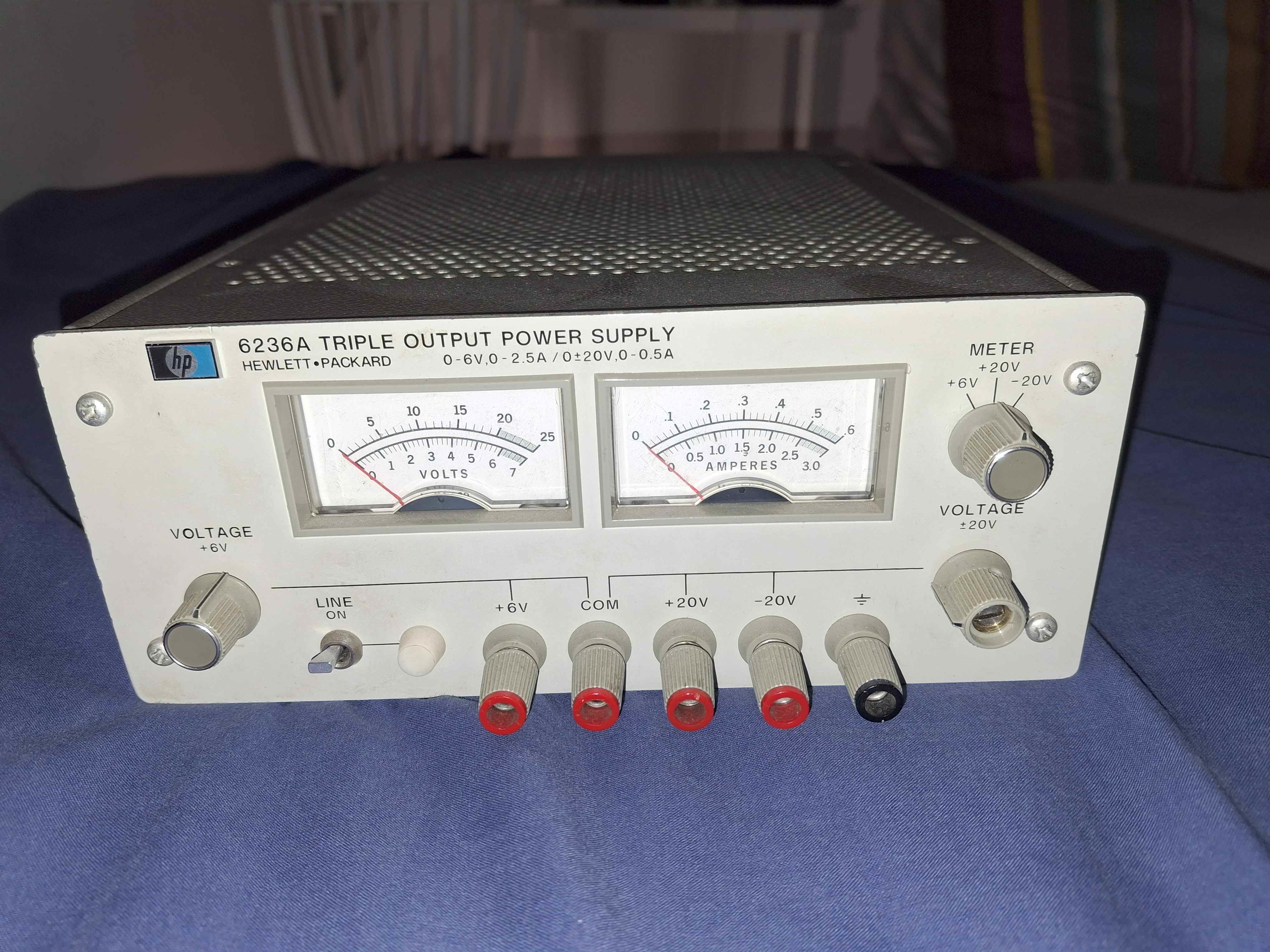
In the early 1980s, I was employed by the American manufacturer HEWLETT-PACKARD, quite well known for products for electronic instrumentation: oscilloscopes and all types of signal generators. It was the moment when this manufacturer was taking the turn towards IT. As an employee, we had the opportunity to buy new products with a 50% discount. It is in this context, quite nice, that I was able to equip my electronics laboratory with the triple HP 6236A power supply and the H 3311A signal generator, which are always operational and of impeccable quality. If you are interested, the detailed feeding manual with the diagram is available free of charge on the website https://hparchive.com/
The development of batteries over the past ten years has been spectacular. The arrival of Li-Po technology allows for high energy densities. We have gone from 30 Wh/kg for lead-acid batteries used to start combustion engine vehicles to 200 Wh/kg for lithium-ion batteries, and even 500 Wh/kg for lithium-sulphur batteries for electric vehicles.
So the idea came to me to take the specifications of the mains version of the HP 6236A to develop an equivalent version, but portable, because powered by a lithium-ion battery.
Principles
Being a fan of ARDUINO's Nano boards, the starting point was to use this MCU to, on the one hand, control the voltage regulators of the two 6V and 20V branches, and on the other hand have a digital interface via a small 2-line screen of 8 characters to display the set voltages and the current flowed.
The second principle is to have only switching regulators in order to maximize the efficiency of the power supplies and obtain the best possible autonomy.
Finally, to have a low volume, I chose as a power source the 7200mAh RC batteries that are easily found on the market.
Table Figure 1 gives the summarized characteristics of this diet.
Technical characteristics
· Balanced 6V -2.5A and +20V/-20V Portable DC Power Supply;
· Voltage Range
o 6V: 0.8 V to 6.0 V
o 20V: +4V to +20V and -4V to -20V;
· RC battery 7200 mAh – 11V1 – 80 Wh;
· Dimensions 145 mm x 80 mm x 80 mm;
· Weight: 730 grams;
· Standard Li-Po charger with external 4-hub JST plug;
· Possibility of having an external 12V battery (Gel Pb or Li-Po);
· Noise
o 6V: < 50mV
o 20V: < 40mV
· Load regulation
o 6V: < 5 mV over the 0 – 6V range
o 20 V: < 50 mV over the 0 – 20V range
· Tracking: +20V and -20V voltages have an accuracy of 1%
· Li-Po source regulation: better than 0.1%
· Resolution
o 6V: 10mV for 0V8 – 70mV for 6V
o 20V: 20mV for 4V – 0.4V for 20V
· Temperature range: 0 to 50°C
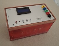
· Two-line 8-character display (6V and 20V voltage – current for 6V)
Figure 1
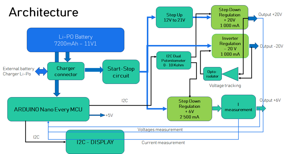
Architecture
Figure 2 illustrates the architecture that was chosen.
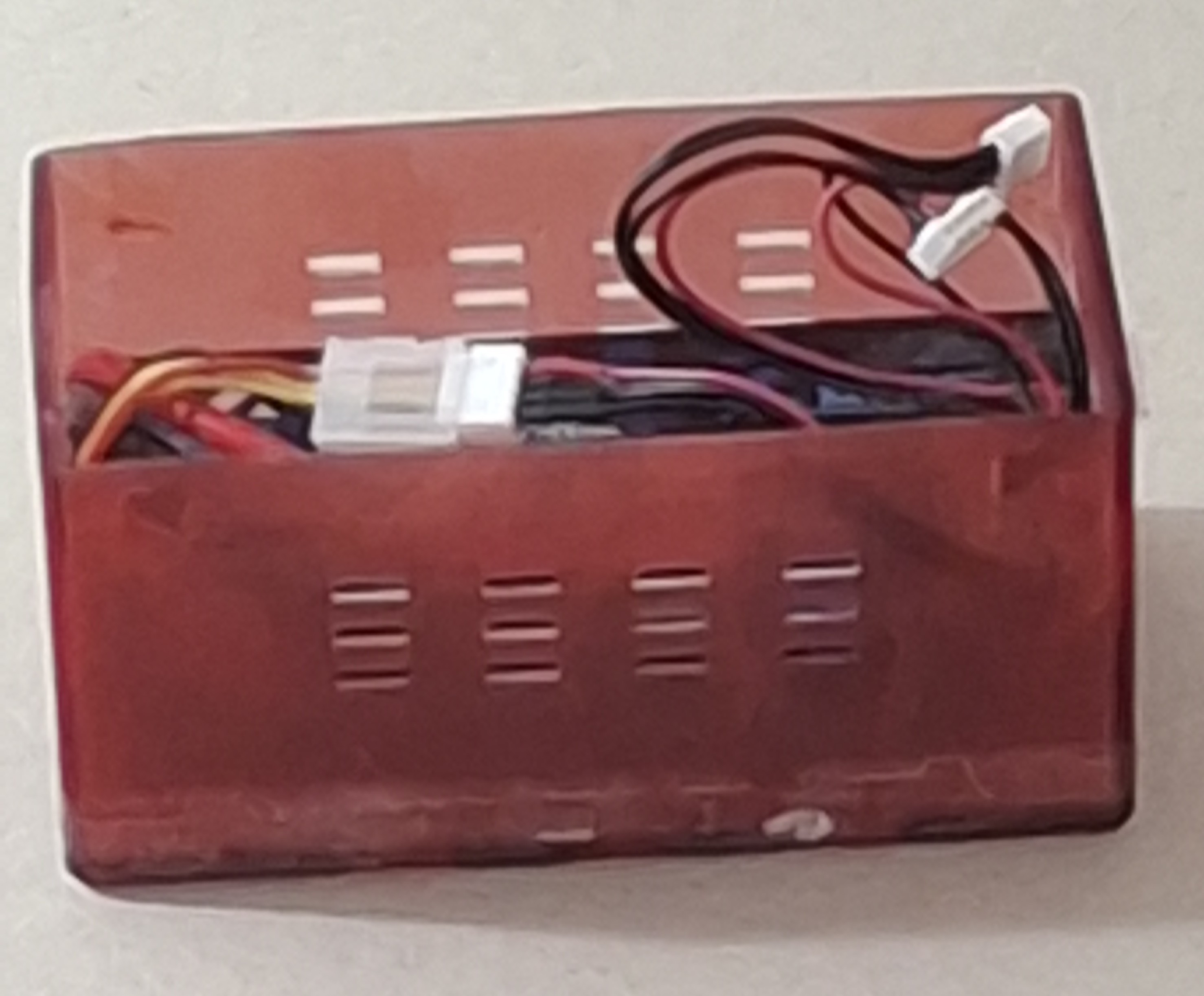
The 3-cell Li-Po power source is connected to two standard 4-pin JST connectors connected in parallel. The first receives the Li-Po battery cable, the second allows via a male-female cable to connect a JST female plug, to the same standard, allowing to connect either a Li-Po charger for this type of battery, or another external power source in parallel with the internal source, which increases the autonomy of the power supply.
An on/off push-button closure detection circuit activates a power MOSFET transistor that acts as a low-through-resistance switch, given the high current that the Li-Po battery can provide.
Figure 2
The 0-6V branch is relatively simple, it is based on a step-down switching regulator whose output voltage is driven by a divider bridge in which there is a digital potentiometer controlled by the MCU via the I2C protocol.
It is very difficult to drive a step-up regulator to generate the second +20V output. As a result, we opted to generate a voltage of 21V from the Li-Po battery, followed by a step-down regulator, which is voltage controlled via the same principle as the 6V source. The use of the potentiometer in the divider bridge deserves an explanation.
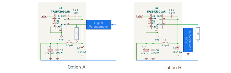
In all diagrams offered by voltage regulator manufacturers, the variable portion is always located between the regulated output voltage and the regulator control amplifier input, as shown in Figure 3 Diagram A. However, if we want the digital potentiometer to be in this configuration, its output must support the maximum voltage that we want to deliver. Very few digital potentiometers have this possibility, and they are very expensive.
By placing the potentiometer in the branch towards the ground of the divider bridge, this need to support a high voltage is avoided, because the regulators all have a reference voltage of around 1.5V. We therefore opted for the diagram of option B for the two 6V and +20V branches. Another advantage is that the components all have, by design, one of the branches of the potentiometer connected to the zero volt (GND).
Digital Potentiometer
Figure 3
But this approach poses a problem, the voltage variation is no longer linear at all with respect to the value of the potentiometer, since the variable part is in the denominator of the formula for calculating the output voltage: Vout = Vref * (R/pot + 1). This results in a variable resolution in the desired range: high when the potentiometer is high, low when the potentiometer tends to zero. We will see a little later, in the diagram, how to reduce (but not eliminate) this disadvantage.
The -20V output branch is controlled by the +20V branch. A dividing bridge between the two outputs with two identical resistors makes it possible to generate a voltage in the middle, which is the difference between the two absolute values. This voltage, via an integrative operational amplifier, will control the diode of an opto coupler. The output of this is used in the divider bridge of the -20V voltage regulator. This loop will make sure that the tracking is perfect by reducing the gap between the two absolute values to zero.
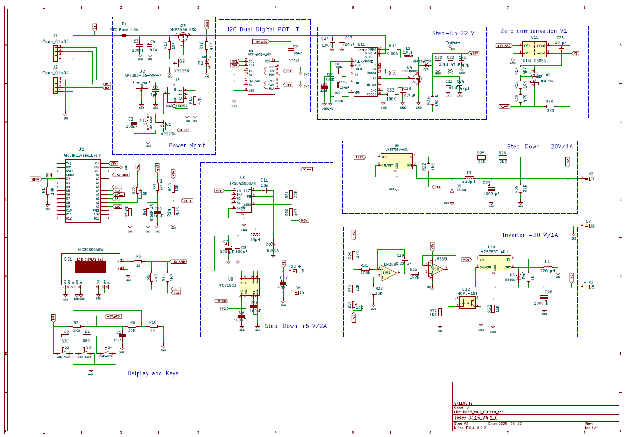
The schematic
The different blocks of the architecture can be found quite easily in the detailed diagram in Figure 4.
In the Start-Stop part, we have added a Li-Po battery protection device equivalent to the BMS circuit that is generally found on the market, either in the form of small separate cards or integrated into the battery packaging. Several points are important about this type of Li-Po battery:
· overload protection;
· protection against deep discharges;
· short-circuit protection;
We have chosen not to integrate a charger into our solution, so the protection against overloads will be the responsibility of the charger you choose. This protection is standard on all charger models.
For deep discharge protection, we use the Arduino Nano MCU to monitor the battery voltage and cut off the power supply by simulating a push button press via the Q1 MOSFET transistor. For short-circuit protection, we have installed a POLY-FUSE fuse calibrated for 1.5 Ampere as input to the power supply.
To have a more linear resolution of the voltages of the two branches 6V and 20V, we have added a fixed resistor in series with the variable part of the digital potentiometers (R20 = 4,700 Ω for the 6V branch, and R22 = 1,500 Ω for the +20V branch).
The so-called zero compensation block reduces the minimum value of the 6V output voltage to 0.8 Volt. This block provides a +4V offset for the R21 measuring resistor of the TPS5430 regulator divider bridge (U6). In order to keep up with the output voltage, this offset is obtained from a DC 5V-5V (U15) isolated power supply.
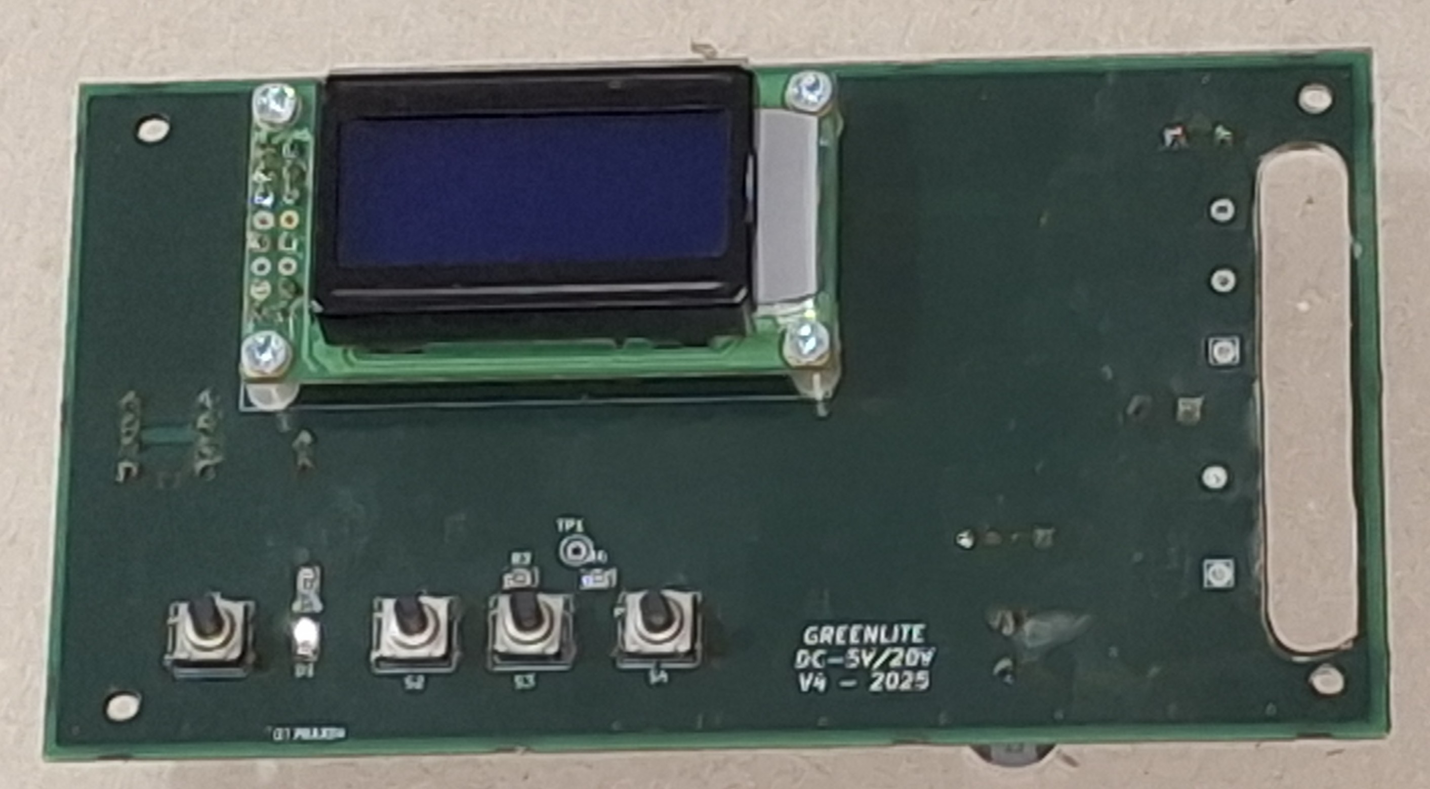
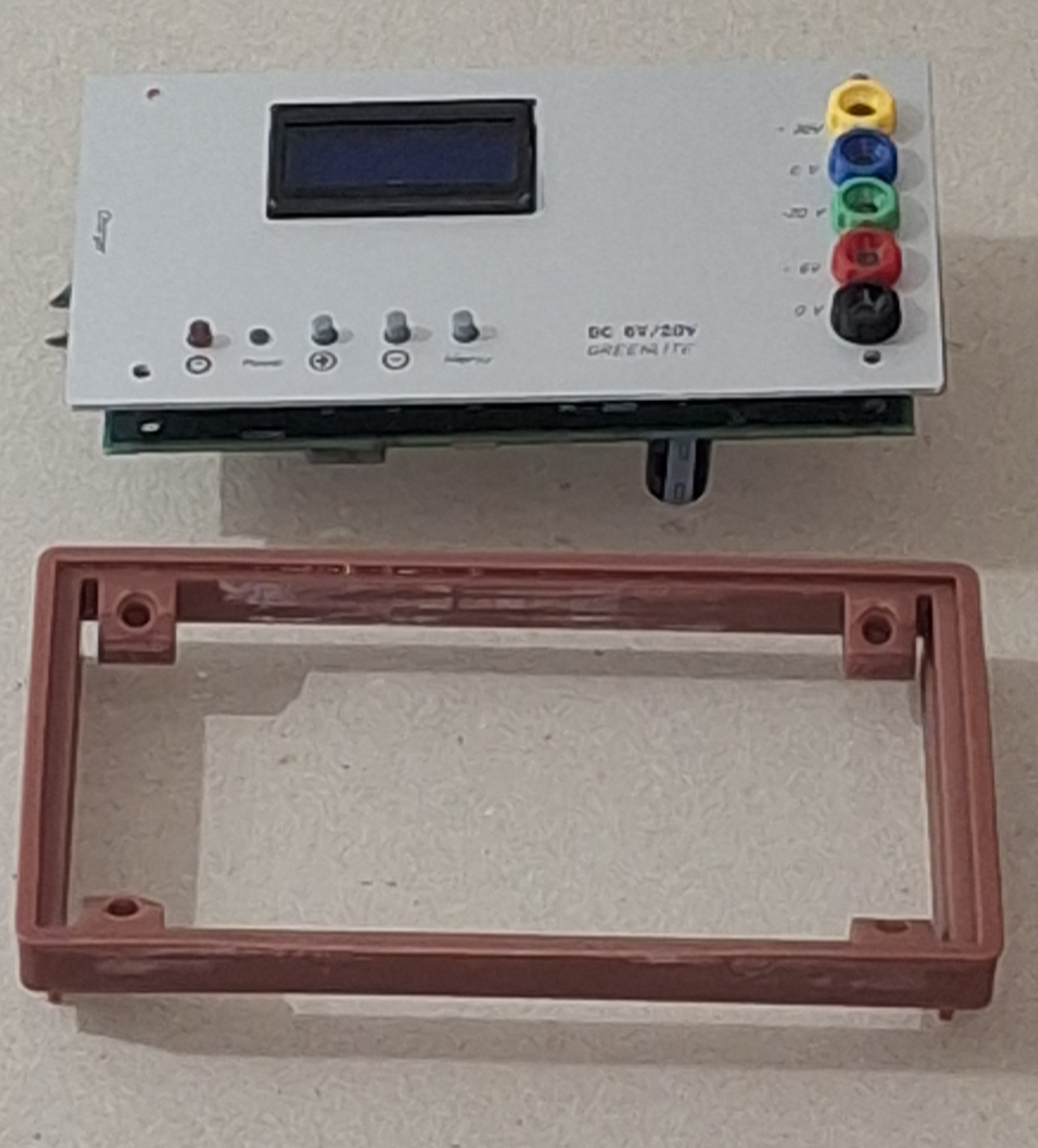
The user interface
It is quite simple:
- at start-up, the display gives the values of the +6V output voltage and the output current;
- the + push button allows you to increase the set value;
- Push button – allows you to lower the set value.
- a long press of one of these two buttons activates an acceleration of the change more or less;
- the last "Menu" push button allows you to change the output value display by giving the 20V branch, and holding down for more than 3 seconds, the value of the Li-Po battery voltage.
The software
It is written in C++ language and structured around 6 modules:
- display management;
- Push button management;
- 6 and 20V voltage measurements and 6V branch current;
- Li-Po battery management;
- dual I2C digital potentiometer management;
- Main program.
The source files are available on the ELEKTOR website along with the schematic and PCB files in KiCad format. Programming is done through the USB B port of the ARDUINO NANO board via the ARDUINO C++ compiler.
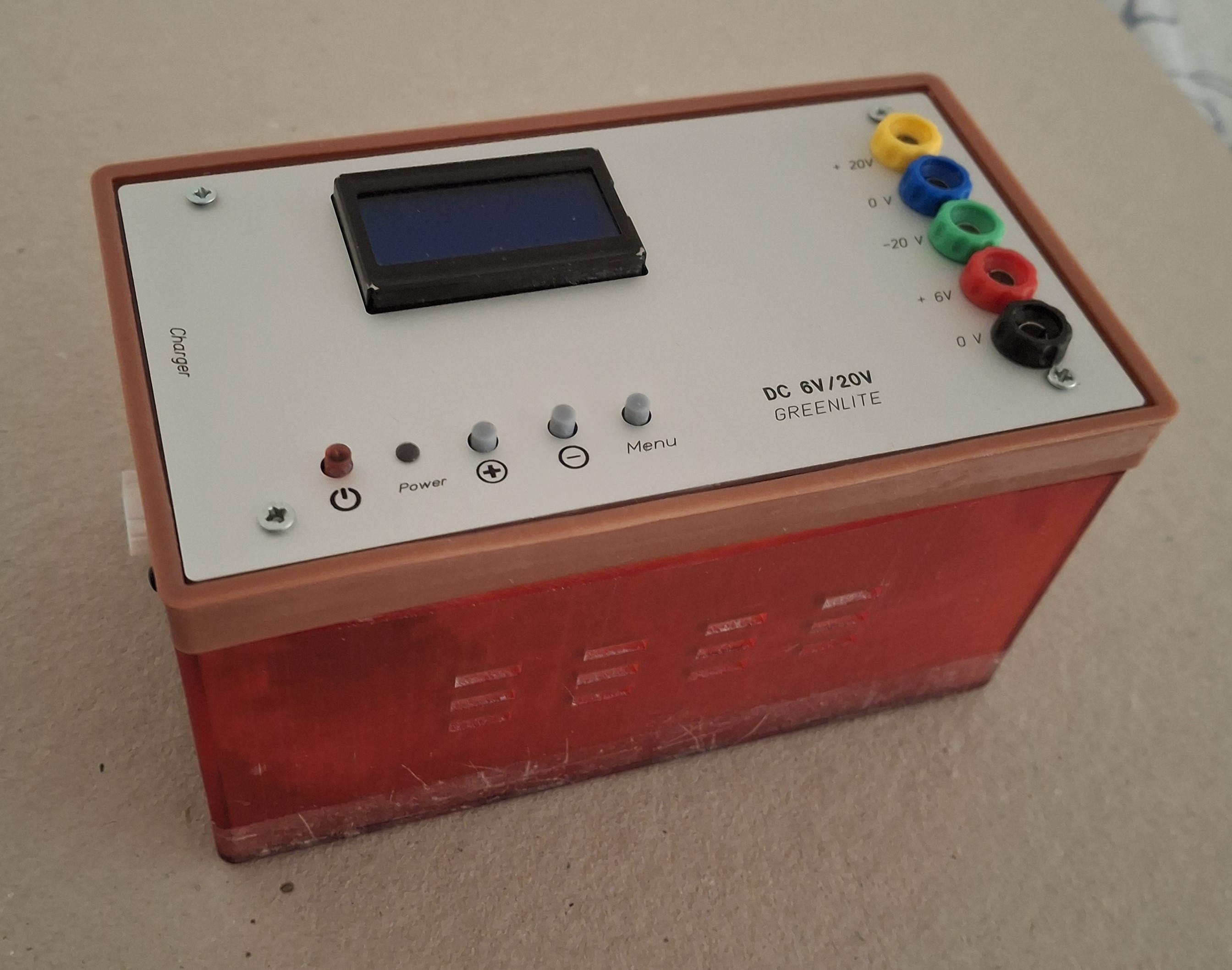
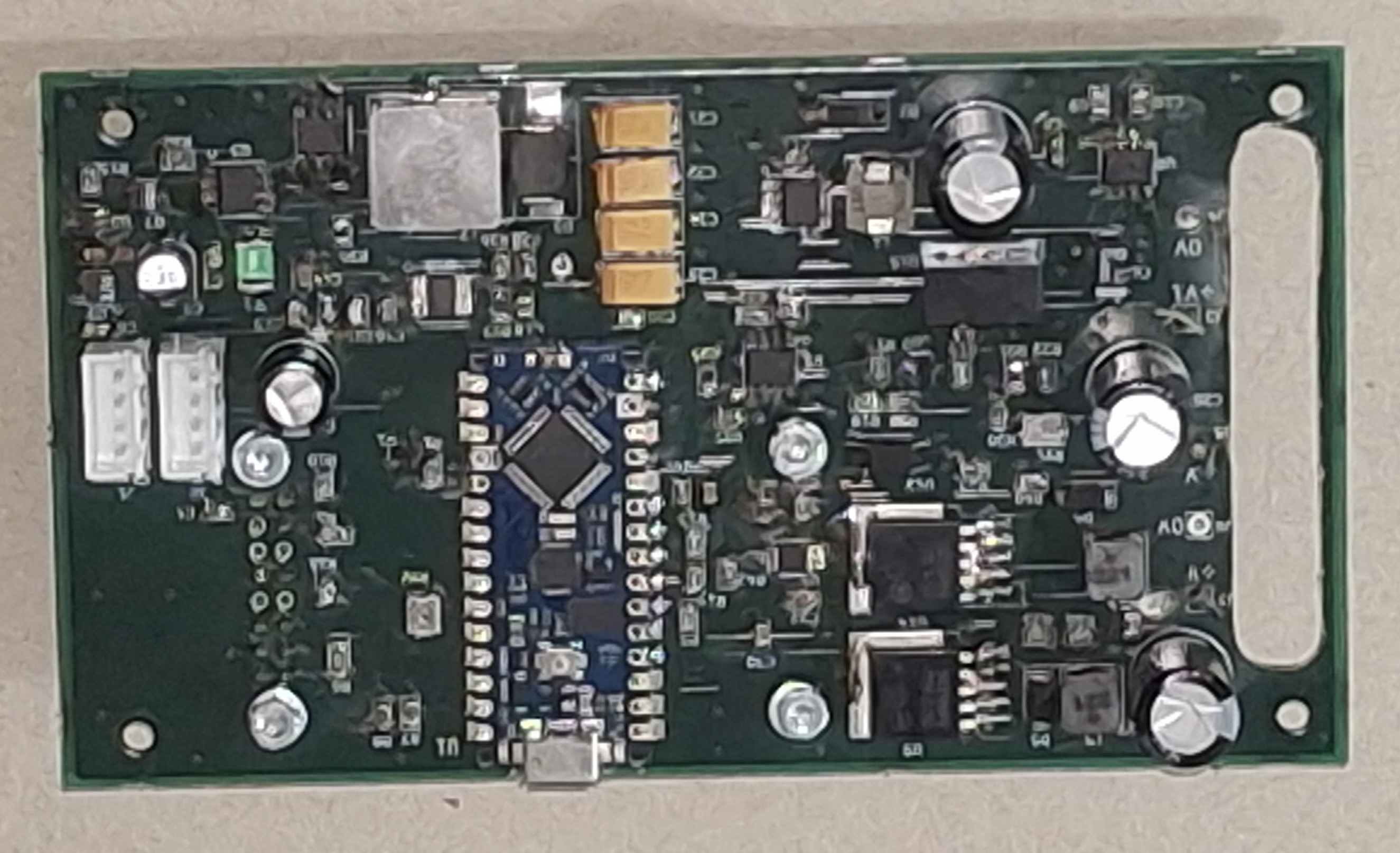
The mechanics
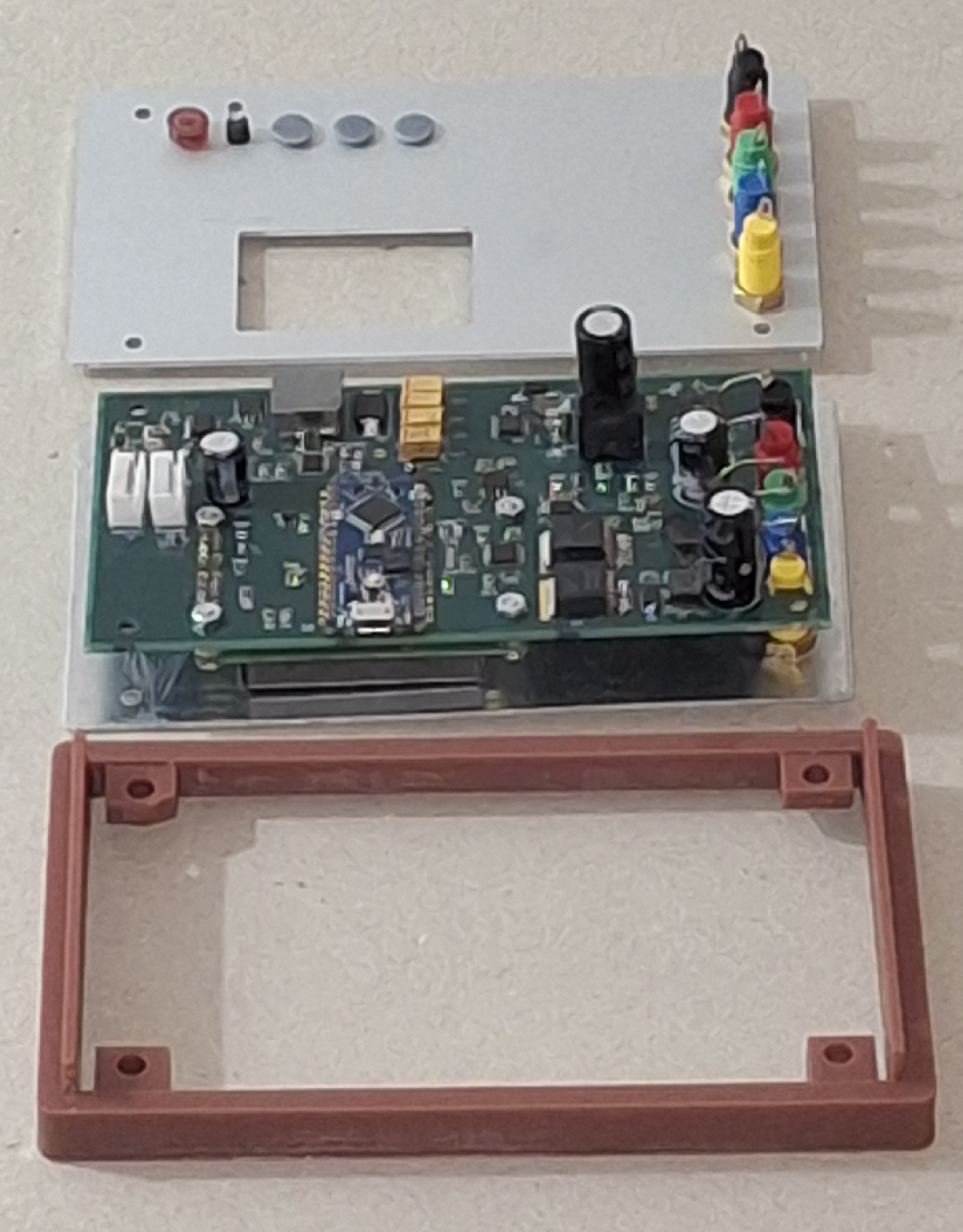
The electronic part fits on a single board made of SMD components that can be welded by hand (Figure 5 & 6).
The three parts of the mechanics are:
· the low support figure 7;
· the upper support figure 8;
· the 4 push button actuators;
They are all made using 3D printing. The corresponding STL files are available on the ELEKTOR website. In addition, you will need a light guide with a diameter of 3 mm and a length of 9 mm.
The front panel can be made from the usual service providers of this type of 1mm thick aluminium support.
Once the two JST cables are plugged into the board's connectors, the top block attaches to the bottom bracket via 4 M2 screws and M2 inserts glued into the 4 3mm diameter holes of the top bracket.
The output terminals are in different colors for ease of use. A diameter of 4mm for banana plugs and wires of good cross-section are recommended to limit voltage drops between the outputs and the circuit that is powered.
Das Elektor Magazine gehört seit 65 Jahren zu den führenden Informationsquellen für Elektronikingenieure, Entwickler, Start-ups und Unternehmen. Unser Magazin wird von einer aktiven Community aus Elektronikingenieuren – von Studenten bis zu Profis – getragen, die mit Leidenschaft innovative Ideen entwickeln und teilen.
Für diese veröffentlichen wir jedes Jahr Hunderte von Beiträgen in Formaten wie Artikeln, Videos, Webinaren und weiteren Lernformaten. Unsere Mission ist es, Wissen auf jede mögliche Weise zu teilen und die Leser mit den neuesten Entwicklungen im Bereich der Elektrotechnik zu inspirieren.
Vielen Dank für Ihre Bewertung!
Kommentar hinzufügen
Vielen Dank für Ihre Bewertung!
Möchten Sie einen Kommentar mit Ihrer Bewertung hinterlassen? Bitte melden Sie sich unten an. Nicht gewünscht? Dann schließen Sie einfach dieses Fenster.

Updates des Autors