
DCH77 Time server
Synchronized by a DCF77 module and backed up by a DS2331 RTC, this time server provides a TTL time signal via an optocoupler and distributes this signal via a 433 MHz transmitter to synchronize alarm clocks throughout the home.
Introduction.
The time signals delivered by the DCF 77 transmitter located in Mainflingen, near Frankfurt am Main, have the advantage, among other things, of automatically tracking the summer and winter time changes. This frees the decoding system from the somewhat complicated programming of tracking these changes.
Unfortunately, the 77.5 kHz frequency is easily affected by interference, and reception can become erratic at great distances from the transmitter.
I have created a time server using the circuit described below based on DCF 77 signals supported by an RTC based on DS3221 based module. The DS2321 uses a temperature-stabilized oscillator, which results in an accuracy of plus or minus 2 ppm at typical home temperatures. DCF synchronization at this level of precision could be dispensed with! However, in the project, it was the I2C interface, which was very economical in terms of the number of connection lines, that was attractive. The heart of the circuit, a PIC 12F1840, offers only 6 input/output lines, which is not very much to drive a display, a keypad, the RTC, the DCF receiver, an opto-isolated DCF output, and a 433 MHz radio transmitter to distribute the radio signal throughout the home.
The Schematic
The schematic, as simple as possible, is shown in Figures 1 for the time server itself and 2 for the display and keypad.
This schematic (figure 1) has three unique features:
The small, inexpensive board implementing the DS3231 is backed up by a 3.6-volt LIR 2032 battery recharged by a very rudimentary circuit. Under normal 5-volt power supply conditions, this circuit leads to an excessively high charging voltage, which is inevitably detrimental to the battery's lifespan. This defect was analyzed in detail in the article "Optimizing the Charging of the LIR 2032" in the August 2024 issue of Special Edition No. 6H. I refer the reader to this article. However, the very simple solution I implemented uses a TL431 programmable voltage reference. The very low power consumption of this circuit, less than 4 µA, its high regulation accuracy and stability, and its adjustment via a single potentiometer make it well suited to the needs.
Decoding DCF signals requires high microprocessor frequency accuracy. The drift must be well below 50 ms over 2 minutes, i.e., a stability of around 10-3. This accuracy is superior to that of the PIC 12F1840's internal clock, which would require the use of a quartz crystal and therefore two circuit pins. Fortunately, the DS3221 offers a 32768 Hz output that can drive one of the microprocessor's time counters. Only one pin is used!
As soon as we have a time reference, it is tempting to distribute it throughout the home. A small 433 MHz transmitter module takes care of this. A very simple homemade protocol, using Manchester-derived coding, sends the current hour and minute every minute. This signal can be used to synchronize, for example, alarm clocks and clock radios, which will be described in other projects.
An opto-isolated output provides the DCF signal to the external world. The optocoupler wiring allows the polarity of the DCF signal to be selected.
To complete this circuit description, a small intervention is required on the DS3221 board. It is necessary to remove either the diode or the resistor from the charging circuit, turn off the board's SQW output, and then solder a small wire between the SQW pin and the battery.
Finally, a note on the choice of the 433 MHz transmitter module. There are two main transmitter models available online. The FS 1000A model used in this assembly offers a range dependent on its supply voltage, up to 12 volts. A 4-pin version, available under the reference WL102, has a compatible pinout despite the additional pin. However, its operating voltage must not exceed 3.6 volts. A circuit adaptation will be necessary if you opt for this module.
The human-machine interface (figure 2) uses a PCF8574 (A) I2C-parallel interface circuit to conventionally control a two-line, 16-character LCD display and four buttons. In an area where the DCF signal is easily received, this interface can be dispensed with, as DCF synchronization can be completed in a few minutes. Where I implemented this device, it can take several days for the DCF signal to be properly received, hence the usefulness of being able to quickly initialize the system.
The Software
The program reads the DCF time every day at 4 a.m., emits a time signal every minute, displays the time every second, and controls the keyboard the rest of the time.
To read a DCF frame, the program first attempts to synchronize to a 100 ms pulse defining a 0. Once this is done, it tracks all the phases of a second (a 100 ms pulse for a 0 or a 200 ms pulse for a 1 followed by an absence of signal until the end of the second) until the missing pulse, which marks the end of the frame. It then accumulates a useful frame for 1 minute.
If the DCF time is read correctly, the program updates the RTC; otherwise, it reads the time from the RTC. It appeared in early versions of the program that it was possible to read a wrong time! In fact, the correctness of the reception is managed using parity bits calculated on the 7 minute bits, the 6 hour bits, and the 22 bits of the remaining date. Two wrong bits for each parity calculation and the parity appears correct. This can happen particularly with the 22-bit message.
To read a DCF bit, the DCF receiver is read every 4 ms. A 100 ms state is therefore represented by a set of 25 measurements. Early versions of the program simply checked the average of the measurements against 12. A higher value indicated a 1, otherwise a 0. The current version of the program seeks tight signal quality. To achieve this, at the beginning of the program, three constants define the expected signal quality:
« SeuilSignal », set to 20, defines the minimum value of the average measurement recognized as a 1
« SeuilSilence », set to 6, defines the maximum value of the average measurement recognized as a 0
« ErreurImpulsion », set to 2, defines the maximum number of false measurements affecting the 800 ms silence between two measurement phases. To further strengthen the frame quality guarantee, the program checks that bit 0 of the frame is set to 0 and that bit 20 is set to 1. Finally, it ensures that the time is in BCD format and that the time components are within their valid value range.
As a result, I no longer recorded any errors, but good synchronizations are rather rare!
Transmission at 433 MHz follows the following protocol:
Transmitting a 1 for 15 ms allows the receivers to wait for a useful signal.
The transmitted message consists of three bytes. The first represents the minutes, the second the hours, and the third is a checksum calculated as the exclusive or of the other two.
The first bit of the transmission is set to one. Then, three cases are possible:
If the next bit is identical, the program emits a pulse with a total period of 800 µs.
If the current bit is 1 and the next two bits are 1 then 0, then a pulse with a period of 1200 µs is emitted.
If the current bit is 0 and the next bit is 1, then a pulse with a period of 1200 µs is emitted.
If the current bit is 1 and the next two bits are 0 then 1, then a pulse with a period of 1600 µs is emitted.
Finally, if the current bit is 0 and the next two bits are 1 then 0, a pulse with a period of 1600 µs is emitted.
This protocol has proven to be very reliable. I successfully compared it with other protocols found on the internet. The range achieved with this protocol was always superior.
The display and keyboard are handled in a very traditional manner.
The program was written in assembler to fit within the available memory. I used Microchip's MPLAB X version 5.35 for its assembly. This is the latest version that supports MPASM assembler, which is much more readable than the XC8 compiler assembler found on later versions of MPLAB X. The programmer used is a PICKIT 3.
Building and Instructions
As a fan of homemade PCB, I designed two single-sided PCBs. Manufacturing the two circuits was straightforward. Soldering the I2C-parallel circuit requires a little care and a fine-tipped soldering iron.
The PIC12F1840 must be programmed before installation.
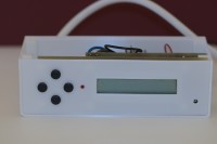
The assembly is installed in a case made with a 3D printer.
Synchronization with the DCF Signal
Upon startup, the device searches for the DCF time. If reception is successful, the LED lights up and the RTC is updated. If unsuccessful, the RTC time is read, and the device will then search for a DCF time reading every hour until a successful reading is obtained.
Then, DCF synchronization is performed every morning at 4:00 a.m.
Manual Clock Setting
Pressing the left key triggers parameter changes in the following order:
Hour
Minute
Second
Time Zone
Time Change Account
Day of the Week
Day of the Month
Month
Year
Parameter changes are made with the left key.
The up and down keys increase or decrease the parameter being adjusted.
The right key exits parameter editing and saves the changed values. If the keyboard is inactive, the program automatically exits parameter editing without saving the changes after 5 minutes.
Build This Project
Bring this design to life with the Elektor PCB Service, powered by Eurocircuits. Upload the project files and order professionally manufactured PCBs or assembled boards through a proven European production platform.
Supporting KiCad, Eagle, Gerber, and ODB++ formats, the service is suitable for everything from prototypes and validation builds to series production and volume manufacturing.
Made in Europe. Fast. Reliable. Professional.
Diskussion (3 Kommentare)