The Elektor LoRa Switch has a nice relay board that can easily be used in Wi-Fi networks if you replace the LoRa part by Wi-Fi. You then get a Wi-Fi Switch.
In the March-April 2020 edition of Elektor Magazine, we published a remote-controlled switch with state feedback that communicated using LoRa. It was housed in a waterproof IP66 enclosure, making it suitable for outdoor use.
It was also a modular project with the relay and power stuff on one board and the LoRa communication circuitry on another.
This interested me, because I was looking for an outdoor switch that could be integrated easily into my home automation system. This system is based on Home Assistant and Wi-Fi, but not LoRa. I am sure it is possible to add LoRa to it, but I didn’t want to dive into that. Instead, I thought that by simply replacing the LoRa module by a Wi-Fi module I could make it run ESPHome, which works great with Home Assistant.
The schematic of the switch board is not very complicated.
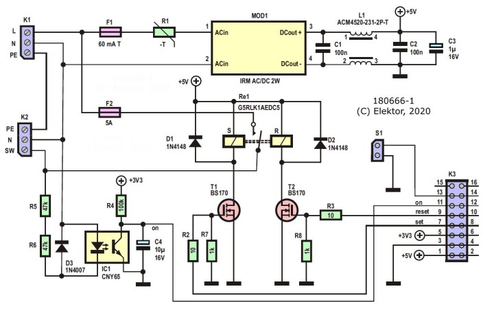
The schematic of the switch board is not very complicated. At the top we have the power supply based on an AC/DC converter MOD1 that provides 5 volts with some protection and filtering things.
In the centre there is a bi-stable relay, RE1, which switches the load on and off. A bi-stable relay is much like a mechanical switch in that it keeps its state even after its power is switched off, exactly like a light switch in your home. It has two control signals, Set and Reset, to toggle its state. These are driven by two MOSFETs T1 and T2 and active-high signals are required.
Note that the relay is protected by 5-amp fuse F2 even though the relay can switch up to 16 amps. The reason for this is that the PCB traces cannot handle that much current, so the fuse protects them against melting. The switch board can handle loads up to about 1 kW.
In the lower left corner, we find an optocoupler IC1 that is in parallel with the load. When the load is switched on, the optocoupler is switched on too. Its LED makes its transistor conduct and the output goes low. When the load is switched off, the output of the optocoupler is high. C4 together with R4 filter out the 50 or 60 Hertz AC signal, ensuring a nice, steady level.
The connector in the lower right corner makes all the required signals available. S1 is intended for a push button mounted on the device so that the switch can also be controlled locally.
A detail to be aware of is that the optocoupler is connected to a 3V3 supply, but there is no 3V3 supply on the board. This voltage has to be provided by control board.
Now we know the specifications for the Wi-Fi control board: it needs two digital inputs, one for the optocoupler and one for S1, and two digital outputs for T1 and T2. It must also provide 3V3 for the optocoupler.
Now, if you say four digital I/O ports and Wi-Fi and 3V3, then you immediately think of the ESP-01 module as it has exactly four GPIO ports and Wi-Fi and it runs from 3V3.
There is a but, however. The four GPIO ports of the ESP-01 must be handled with care, because they also determine how the module will work after power-on. For normal operation, GPIO0, GPIO1 and GPIO2 must be high at power-on. This is mentioned in the notes below the ‘Pin Definitions’ table in the datasheet of the ESP8266EX. Many ESP8266 users are aware of the requirements for GPIO0 and GPIO2, but not everybody knows of the one for GPIO1 better known as TXD, the serial output.
On the switch board, two of the four control signals are always low at power-up, ‘Set’ and ‘Reset’, due to resistors R7 and R8. However, the ‘On’ signal can also be low when the load is switched on when the module powers up. This is possible because the relay is bi-stable and keeps its last state, even when the power is off.
Input S1 is floating, its state at power-up is determined by the control board unless someone happens to press the push button when the system powers up.
So, all in all, we are dealing with four signals that can all be low at power-up that must be connected to four pins three of which must be high at power-up. Using an ESP-01 module in this situation therefore is a challenge.
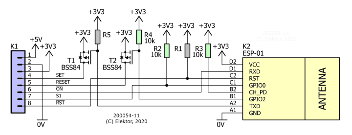
A possible way to connect an ESP-01 module to the LoRa Switch board.
The solution I came up with is as follows:
RXD or GPIO3 is the only pin that can be freely connected, I therefore connected it to the output of the optocoupler because its level at power-up is unpredictable. RXD is going to be an input.
When GPIO0 is low at power-up, the module will boot in Flash programming mode. This can be useful for updating the firmware, so I connected it to S1. So, GPIO0 is going to be an input too.
GPIO2 and TXD or GPIO1 are now left over and therefore have to become the outputs. To decouple them from the low impedances created by R7 and R8 on the switch board, I inserted P-MOSFETs with a pull-up resistor on their gates. This ensures that at power-up GPIO2 and TXD will see a high level. When the ESP-01 has finished booting, they can be configured as active-low outputs.
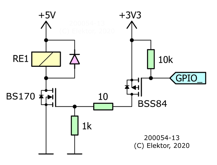
The output driver: a P-MOSFET drives an N-MOSFET.
The output driver now looks like this. When the GPIO signal goes low, the P-MOSFET BSS84 will conduct. This will pull the gate of the N-MOSFET BS170 high, so it will conduct too, and the coil of the relay is powered. When the GPIO signal is high, the P-MOSFET BSS84 will block. The N-MOSFET BS170 will now also block due to the 1k pull-down resistor at its gate, and the relay coil is not powered.
The 10k resistor ensures that the GPIO pin is pulled high at power up.
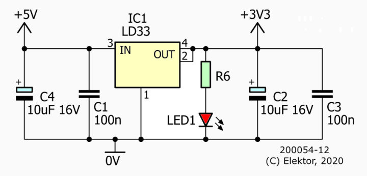
A simple 5 V to 3.3 V adapter.
For the 3V3 power supply, I simply added a low-dropout regulator.
In practice R1, R6 and LED1 are not required as they are already included on the ESP-01 module. R5 is not needed either, but I added it just in case.
ESPHome YAML File
With the in- and outputs defined, we can write the ESPHome configuration YAML file. This is a bit more complicated than usual due to the bi-stable relay that needs two pins instead of one. ESPHome and Home Assistant do know a so-called ‘cover’ component that can control such peripherals, but it is intended for garage doors and window blinds and the like that have an open and a close button. They also have a special icon.
Our switch is just a switch and so we want it to behave like a switch and look like one. This can be done with a template switch that allows you to specify the behaviour for turning on and turning off separately.
# Enable fallback hotspot (captive portal) in case wifi connection fails
ap:
ssid: "Wifi-Switch (pw=12345678)"
password: "12345678"
captive_portal:
# Logging is not possible on default UART0 pins as GPIO1 & GPIO3 are
# used for switches & sensors.
logger:
#hardware_uart: UART0_SWAP
baud_rate: 0 # hardware uart off.
# Enable Home Assistant API
api:
# Enable Over-the-Air programming
ota:
output:
- platform: gpio
id: relay_set
pin: GPIO1 # TXD, may not be pulled low at startup (see datasheet ESP8266EX).
inverted: true
- platform: gpio
id: relay_reset
pin: GPIO2 # Do not pull low at startup.
inverted: true
switch:
- platform: template
name: "Wi-Fi switch"
id: wifiswitch
turn_on_action:
# Pulse the Set pin.
- output.turn_on: relay_set
- delay: 0.1s
- output.turn_off: relay_set
turn_off_action:
# Pulse the Reset pin.
- output.turn_on: relay_reset
- delay: 0.1s
- output.turn_off: relay_reset
# Use optocoupler state as switch state.
lambda: return id(optocoupler).state;
# Pushbutton & optocoupler.
binary_sensor:
- platform: gpio
name: "Wi-Fi switch pushbutton"
id: pushbutton
pin:
number: GPIO0 # Do not pull low at startup.
inverted: true
on_press:
then:
- if:
condition:
binary_sensor.is_on: optocoupler
then:
switch.turn_off: wifiswitch
else:
switch.turn_on: wifiswitch
- platform: gpio
name: "Wi-Fi switch optocoupler"
id: optocoupler
pin:
number: GPIO3 # RXD, the only ESP-01 pin that may be pulled low at startup.
inverted: true
First, we define GPIO1 or TXD as an inverted output named relay_set and GPIO2 as an inverted output named relay_reset. We also define GPIO3 as an active-low binary sensor for the optocoupler.
Then we specify a short 100 ms pulse on the relay_set output as a turn-on action and do the same on the relay_reset output as turn off action. As switch state we return the state of the optocoupler.
To make push button S1 work as expected, meaning that pressing it will toggle the load on and off, we define GPIO0 as an active-low binary sensor. When it is pressed, the state of the optocoupler is checked first. If the load is active then we switch the relay off, if the load was inactive, then we switch it on. An 'if-then-else' clause will do the trick here.
After compiling ESPHome with this YAML file and flashing the ESP-01 module, the Wi-Fi Switch should pop up in Home Assistant and is ready for automation.
Want to build a project?
Bring your design to life with the Elektor PCB Service, powered by Eurocircuits. Upload the project files and order professionally manufactured PCBs or assembled boards through a proven European production platform.
Supporting KiCad, Eagle, Gerber, and ODB++ formats, the service is suitable for everything from prototypes and validation builds to series production and volume manufacturing.
Das Elektor Magazine gehört seit 65 Jahren zu den führenden Informationsquellen für Elektronikingenieure, Entwickler, Start-ups und Unternehmen. Unser Magazin wird von einer aktiven Community aus Elektronikingenieuren – von Studenten bis zu Profis – getragen, die mit Leidenschaft innovative Ideen entwickeln und teilen.
Für diese veröffentlichen wir jedes Jahr Hunderte von Beiträgen in Formaten wie Artikeln, Videos, Webinaren und weiteren Lernformaten. Unsere Mission ist es, Wissen auf jede mögliche Weise zu teilen und die Leser mit den neuesten Entwicklungen im Bereich der Elektrotechnik zu inspirieren.
Vielen Dank für Ihre Bewertung!
Kommentar hinzufügen
Vielen Dank für Ihre Bewertung!
Möchten Sie einen Kommentar mit Ihrer Bewertung hinterlassen? Bitte melden Sie sich unten an. Nicht gewünscht? Dann schließen Sie einfach dieses Fenster.


Diskussion (0 Kommentare)