
Wassercomputer / Watercomputer
for the english version please scroll down...Hallo,ich war schon sehr genervt, da ich mit dem Bewässern des Grundstücks mehr Zeit verbracht habe als mit meinen elektronischen Projekten.Bis ich dann dieses Projekt umgesetzt habe. Genau genommen ist es eine 12 fache Zeituhr mit 12 Relais um die Ventile anzusteuern.
for the english version please scroll down...
Hallo,
ich war schon sehr genervt, da ich mit dem Bewässern des Grundstücks mehr Zeit verbracht habe als mit meinen elektronischen Projekten.
Bis ich dann dieses Projekt umgesetzt habe. Genau genommen ist es eine 12 fache Zeituhr mit 12 Relais um die Ventile anzusteuern.
Das Projekt besteht aus 3 Platinen: eine Netzteilplatine, eine Relaisplatine und eine Platine mit Mikrocontroller und GLCD um die 12 "timer" einzustellen. Die Schaltungen und Platinenlayouts für die Netzteil- und Relaisplatine habe ich selber entworfen. Die Platine mit dem Mikrocontroller und dem GLCD habe ich von “mikroelektronika” erworben, es ist das “smartGLCD 240x128.
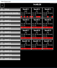
Das Display zeigt 3 Seiten, auf Seite 1 werden die Ventile 1-6 dargestellt. Auf Seite 2 die Ventile 7-12 und auf der dritten Seite ist es möglich die aktuelle Zeit einzustellen. Die Hintergrundbeleuchtung ist weiß, bzw. schaltet sich die Hintergrundbeleuchtung bei Inaktivität aus.
Auf der Seite 1 kann man den aktuellen Zustand der Ventile 1-6 erkennen, oben wird die aktuelle Zeit und Raumtemperatur angezeigt.
In dem linken oberen Rechteck kann man folgendes ablesen:
german english
Ventil 1 valve 1
AUF ZU OPEN CLOSE Ventil ist geöffnet o. geschlossen
12:30 05 12:30 05 Startzeit und Laufzeit
EIN AUS ON OFF Zeitfunktion Ein-/Ausschalten
Wenn das linke obere Rechteck angeklickt wird öffnet sich die Seite zum einstellen des Ventils (auf dem Foto Ventil 8). Hier lässt sich die Startzeit und die Laufzeit von 5 Minuten bis 60 Minuten einstellen. Anschliessend wird unten die errechnete Endzeit angezeigt. Wenn die Zeitschaltfunktion nicht benötigt wird (weil es regnet), lässt sich diese links ausschalten. In der linken unteren Ecke der Seite gibt es zwei Button um das Ventil manuell zu öffnen oder zu schliessen. Auf dieser Seite ist die Hinterdrundbeleuchtung grün oder rot. Dies dient als Zustandsanzeige des Ventils, grün ist Ventil geöffnet und rot Ventil geschlossen.
Auf "photo 1" ist die Netzteilplatine zu erkennen.
Auf dem "2nd photo" sieht man die Relaisplatine (auf dem Foto und im Schaltplan sind 13 Relais zu sehen, das letzte Relais ist für die Pumpe gedacht, aber ich nutze es im Moment nicht).
Ich arbeite zur Zeit an einer neuen Version von diesem Projekt. Bei dem neuen Projekt wird die GLCD-Platine durch ein PIC32 und eine Ethernetplatine ausgetauscht. Ich habe auch schon ein Screenshot von der Software eingefügt.
Hi,
I was so stressed out lately because I didn’t have enough time for my electronic projects.
Because I had to spend a lot of time to water my lawn and plants. And standing there, I came up with a very good working solution…
Now,(since I have time) I want to present my new project: a watercomputer.
It is a normal 12 times timer with 12 relay outputs to control the water valves.
The project consist of 3 boards: 1 board for power supply, 1 board with the relays and 1 board with the controller and touch glcd to setup the 12 timer.
I created the schematic and pcb layout of the power and relay board by myself.
The board with the controller is from “mikroelektronika” it is the “smartGLCD 240x128.
The display will show 3 top pages. One page for valve 1-6 and one page for valve 7-12 and one page to set the actual time. The backlight of the tree pages will be white or off (to save power).
In picture one you will see the first page for valve 1-6 the actual time and room temp.
Let me explain the upper left rectangle what you see on page one.
german english
Ventil 1 valve 1
AUF ZU OPEN CLOSE valve is opened or closed
12:30 05 12:30 05 you see the start time and the runtime
EIN AUS ON OFF the timer function is on or off
If you touch on the upper left rectangle, for example, you will see the setup page for valve 8.
You can set the start time here and also the runtime from 5 minutes to 60 minutes and you will see the end time. If you don’t need the timer (because it’s raining) you can switch off the timer on the left site of the page. If you want to open or close the valve manually you can touch the button in the down left corner of the page. If the valve closed the backlight of the glcd will be red and if the valve is open the backlight will be green (it is for the feedback).
in photo 1 you will see the board for power supply
in the 2nd photo you will see the relay board ( in the photo or schematic you can see 13 relays, the last relay was for the pump, but I don’t need it now).
I’m working on the next version of this project. The new project is without a glcd but it works with a Pic32 and a Ethernet communication board . I added a photo from the desktop app.
Updates des Autors