
Robust RTD-based Thermometer
Do you need to measure temperature in a harsh environment? Do you like the linearity that an RTD provides? If the answer is Yes, read on.
This project is based on the article by Mark Driedger titled Build an Accurate Milliohm Meter in Circuit Cellar, Sept 2016. He uses the synchronous rectification technique and a 16 bit ADC to measure resistance very accurately. I built that project and was very pleased with the resulting instrument.
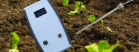
Recently I had the need to measure soil temperature. I first used a mercury thermometer and was frustrated with the difficulty reading it; the light was poor and the plants were on the floor making viewing the thermometer tough. It was at this point I decided I needed an electronic thermometer with an easily readable display! But this one had to have a sensor I could stick in the dirt; better yet if I could put the sensor into a liquid. What about being able to measure the temperature of a roast on the BBQ?
I happened to have a couple of industrial grade RTDs that have been waiting for a project; one of them would be used here. It was about this time I realized I had recently worked with a circuit that would be ideal for measuring the resistance of an RTD. Also, when I bought parts for the Milliohm Meter I bought an extra case, ADC breakout board, OLED and Pro Mini. All the parts I needed were at hand so the new project could proceed.
Since this is a one-off project there was no justification for a PCB. When I build one-off projects I like to use wire wrapping for the circuit board. However, the long wire wrap leads require extra space, which often isn’t available. Such was the case here. Then I have to resort to point to point wiring with each joint soldered. This means even a simple project requires a lot of time and tedious wiring. A PCB would sure make this project come together quickly! Anyway, with careful work and frequent testing I was able to get the circuit working. Once it would measure resistance correctly it was ready for the RTD.
Connecting the RTD to the cable turned out to be something of an adventure. The 4 wires at the back of the RTD probe body were made of a material which just would not solder. So I had to resort to crimp terminals for the RTD to cable connection. This made the connection area much larger than I had planned; an unfortunate reality. You’ll see that if you look at the probe photo.
It’s difficult to cut a hole for a display in the top half of a curved case when the display is attached to the bottom half and have the hole end up where it needs to be. You can see in the photo with the case open that I used layout dye to help with the process. (Actually a permanent felt marker.)
The schematic for the RTD Thermometer has been attached as a Design Spark schematic zipped. Although I have the schematic as a PDF, even this simple circuit produces a PDF larger than the 5 MB maximum imposed. The schematic shown here is essentially Mark’s schematic redrawn with minor changes reflecting how I built and modified it for this project.
The code that is attached here is also essentially Mark’s code with appropriate changes for this project. The most notable change/addition is the calculation of temperature from measured RTD resistance. The function to display the temperature is also different.
It would be appropriate to calibrate the thermometer using boiling water and ice water. For now I’ll rely on the accuracy of the resistance measurement and the reliable RTD relationship.
This is a very nice instrument if you need a rugged accurate thermometer.
Updates des Autors