
Hob2hood interface investigation
A little automation for your kitchen by coupling your extractor hood to your induction cooktop.
Introduction
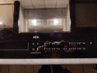
It all started after I installed a new induction cooktop into our kitchen. It turned out that it contains the function "hob2hood", which automatically switches the extraction hood depending on your cooking activities. Nice!!!
The interface between cooktop and hood is realised with infra-red and on the internet some solutions using Arduino can be found. But ... looking at the codes found, I am sure that this works just by incidence and a new version of the IR-library may or may not be working any more. Therefore some more investigation was needed.
The first step in such situations: connect an oscilloscope to an IR-receiver and look what is received (photo hob2hood_signal). Comparing the results of all scope-pictures I come to the conclusion that a simple serial stream of 24 data-bits is sent preceded by a single start-bit and no stop-bit(s). Moreover I don't think this is a NRZ datastream. The codes can be found in the table below. It may be possible that some or all bits have to be inverted, but that will have no impact on the result. The results of this investigation form the basis for the next steps in my project.
---------- table of data streams -----------
on: 1 00101101 00101100 00101011 = 2d 2c 2b
off: 1 00101010 00101001 00101000 = 2a 29 28
v0: 1 00100111 00100110 00100101 = 27 26 25
v1: 1 10010011 10010010 10010001 = 93 92 91
v2: 1 10010000 10001111 10001110 = 90 8f 8e
v3: 1 00011110 00011101 00011100 = 1e 1d 1c
v4: 1 10001101 10001100 10001011 = 8d 8c 8b
Test transmitter
Electronic hobyists are lazy people, and so am I. I didn't want to go to the kitchen every time a test of my software was required. Therefore I needed a simple IR remote-control which generates the same codes as my induction cooktop and also any code will be sent 3 times. This device is realised with a small PIC12F1822 microcontroller and a quick-and-dirty program. I checked the output on the oscilloscope and to be completely sure also on an Arduino with an IR-receiver sketch. Because I don't own an extractor hood with hob2hood functionality (in that case this project was unnecessary) the remote control is not tested on an official target. Maybe some Elector reader is able to do this ;).
The remote-control has 3 pushbuttons: light off, light on and speed 0-1-2-3-4. As power supply I used 3 AAA batteries, but a small USB charger will also work. There is no PCB design; it is realised on a small piece of veroboard. D1 is the IR-Led which sends the data with 38 kHz modulation. D2 is a normal Led which shows the activity of the transmitter; D2 can eventually be omitted. From pin 2 the output signal without the 38 kHz modulation can be obtained for testing purposes.
Test receiver
Next step is an IR-receiver with an LCD-display to check the data received. Because this device is not important for the final result, only the program and the electronic circuit are presented here. No design details. The receiver is realised on my PIC+LCD test board (https://www.elektormagazine.nl/labs/prototype-board-for-microcontroller-with-lcd), using a PIC16F1847 microcontroller. The final program will be based upon the program of this test receiver.
Final circuit
The decoder is also realised with a PIC12F1822 microcontroller. The program is a simplified version of the test receiver without LCD display. Because my extractor hood has 3 different speeds, I needed 4 outputs (1x light and 3x speed). Level 1 switches the low speed, level 2 and 3 both switch the middle speed and level 4 (manual control on the cooktop only) switches the -very noisy- high speed of my hood. The microcontroller is connected to a 4 relais PCB from Banggood to drive the high voltage part. Current consumption of the (inverted) inputs is only 2mA; therefore the microcontroller can drive the outputs directly.
Because I use low-voltage programming the reset-pin cannot be used as output. If high-voltage programming is used, eventually an additional ouput is available. That way all speed steps can be decoded separately.
The circuit has only a small number of components and therefore is also realised on veroboard. The decoder and relais board both need 5 VDC, which is provided by an old USB charger.
The high voltage part contains a double pole, 3 position switch to select between manual-off-automatic mode. In manual mode the hood works as original intended by the manufacturer, off means completely off and in automatic mode the hob2hood interface is in charge. Because there are lots of different hoods the schematic of the high-voltage part is not included.
Updates des Autors