
Inductor Tester - Part 2 | Saturation Assesment
Inductors may loose their inductance at higher currents because of core material saturation, which limits the range of use. This is a second part of the description of a versatile simple inductor tester to be used in combination with a digital oscilloscope (https://www.elektormagazine.com/labs/simple-tool-to-assess-inductors-and-transformers-with-100nh-l-100h). This part pertains the quick assessment of non-linearities and saturation effects of small inductors. Giving hints on the maximum usage currents.
Inductors that contain magnetic cores are subject to non-linear behaviour due to the magnetisation (hysteresis) properties of the core material. The detailed properties of a specific inductor depend on the material properties and its geometry and the number (and position) of winding turns. Typical effects are the loss of inductance with increasing current, sensitivity of the inductance on external magnetic fields, inconsistent results of inductance measurements by different measurements (size of excitation). The main cause is the maximum possible magnetisation of the core material leading to saturation beyond a strong enough excitation (=current windings).
Here a tiny circuit is presented that in combination with an oscilloscope allows a quick assessment of the saturation approach. The circuit suddenly applies a voltage to the inductor under test and “measures” the current via a (small) voltage across a shunt resistor. Due to the inductance the current starts a zero and increases more or less linearly with time. As soon as this current i.e the shunt voltage voltage exceeds a preset limit the applied voltage will be cut off. After a waiting time of some 100 ms the cycle is repeated.
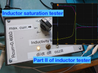
Monitoring the current rise in the inductor with the oscilloscope allows easy assessment of the non-linearities and saturation effects. Examples are shown below. Further quantitative analysis (also shown below) may yield inductance values as function of current. However, combined with the pulse excitation ringing frequency test to get the inductance value and the current-increase test described here combined in a tester (shown in figure 1) allows to get a comprehensive quick impression on the kind of inductor.
All relevant information (schematics, explanation, test) are compiled in the attached file InductanceTester_II.pdf.
Here a tiny circuit is presented that in combination with an oscilloscope allows a quick assessment of the saturation approach. The circuit suddenly applies a voltage to the inductor under test and “measures” the current via a (small) voltage across a shunt resistor. Due to the inductance the current starts a zero and increases more or less linearly with time. As soon as this current i.e the shunt voltage voltage exceeds a preset limit the applied voltage will be cut off. After a waiting time of some 100 ms the cycle is repeated.
Monitoring the current rise in the inductor with the oscilloscope allows easy assessment of the non-linearities and saturation effects. Examples are shown below. Further quantitative analysis (also shown below) may yield inductance values as function of current. However, combined with the pulse excitation ringing frequency test to get the inductance value and the current-increase test described here combined in a tester (shown in figure 1) allows to get a comprehensive quick impression on the kind of inductor.
All relevant information (schematics, explanation, test) are compiled in the attached file InductanceTester_II.pdf.
Diskussion (4 Kommentare)