
DC motor speed controller for RC models
There are many RC models (airplanes, motor gliders, boats, cars etc.) powered with DC motor. DIY simple, one direction, speed controller.
One day my grandson got a small RC fast boat. The installed RC system has On/Off commands for the motor speed and a rudder making fast boat difficult to control especially for beginners like my grandson (7).
To improve the fast boat control, I decided to replace the original On/Off RC system with a proportional RC system which I use to control my airplane models.
With some mechanical modification, a proportional servo for the rudder was installed, and the next step was to install the receiver and speed controller for DC motor.
Unfortunately, all my airplanes use combustion engines and I do not have any controller for DC motor at home.
We went to the shop with RC models and accessories to buy a motor controller. However, they did not have a controller on stock and the delivery would take 5 days. Too long, my grandson and me wanted to play with the boat during the weekend.
As I play with electronics and PIC programming, I tried to make a speed controller by myself in a shorter time.
To keep things as simple as possible, I decided to make one direction speed controller. In case of a car model, forward/reverse is important, while, for a fast boat reverse is not important.
After two days of intense work, the motor controller was done.
Principle of operation
Servo and motor controller are controlled with digital PWM signals with a 50 Hz frame rate. Within each 20 ms timeframe, there is an active-high digital pulse controlling the servo position and motor speed. Every pulse nominally ranges from 1.0 ms to 2.0 ms, depending on joysticks position on the RC transmitter unit.
Motor controller hardware
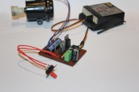
Schematic and PCB was designed based on the components I had at home.
Electronic circuit is very simple and easy to understand.
Low drop voltage regulator LX8383A-00 gives 5.5V supply for receiver, rudder servo and PIC. Supply voltage is stable as long as the battery voltage is over 6.5V.
The maximum PIC operating voltage is 5.5V and will ensure the highest possible Q1 gate voltage and the lowest drain – source On resistance. Reverse diode D1 is the 3A type which is enough in my case. If higher motor current is required, Q1 and D1 should be chosen accordingly. Keep in mind to select MOSFET with low gate On voltage.
LED function will be explained later.
I had a few different 8 pin PICs on stock. The best choice was 12F683, due to the timer with the external control gate and the PWM module which simplifies PIC software.
Motor controller software
Source code is written in the assembler.
Control pulse from the receiver output is connected to Timer1 control gate. When the pulse is in high state, the internal clock increments Timer1. When the pulse state changes to low, increments stop with interrupt. Interrupt routine reads the value in Timer1, saves it for calculation and clears Timer1. Program loop calculates new value for PWM and writes it to CCPR register. Depending on the value in the CCPR register, PWM outputs an active-high pulse width change, keeping Q1 shorter or longer in On state and as a result, the motor speed changes. The mentioned process repeats every 20ms.
To minimize calculations, PWM frequency is not fixed and depends on the difference between the min and max pulse width values. Those values are measured during the motor controller power On initialization and the difference is saved in the PR register which defines PWM frequency. If the difference is 1ms, PWM frequency will be the lowest, 4.3 kHz. If the difference is less than 1ms, the frequency will be higher. The minimum acceptable difference is 0.4 ms, as is defined in the software and the PWM frequency is limited to 10.7 kHz. The PWM frequency does not affect motor operation.
Motor controller power On
To ensure correct motor controller initialization and operation always follow power On procedure:
Safety stop function
If during the operation control pulses disappear (transmitter signal has been lost), the controller will stop the motor and wait for the control pulses to appear again.
Conclusion
The designed DC motor speed controller works perfectly.
The components enable “easy to do” homemade PCB, simple soldering and “out of circuit” PIC programming.
The motor controller can be easily modified for any required motor currents and voltages and can be used for DC motor control in small airplanes, motor gliders and other applications where one direction motor control is acceptable.
The PCB can be redesigned for SMD components if motor controller dimensions are critical.
I suggest head sink installation on 5.5V regulator if battery voltage is 12V or higher and/or more than one servo is in use.
To improve the fast boat control, I decided to replace the original On/Off RC system with a proportional RC system which I use to control my airplane models.
With some mechanical modification, a proportional servo for the rudder was installed, and the next step was to install the receiver and speed controller for DC motor.
Unfortunately, all my airplanes use combustion engines and I do not have any controller for DC motor at home.
We went to the shop with RC models and accessories to buy a motor controller. However, they did not have a controller on stock and the delivery would take 5 days. Too long, my grandson and me wanted to play with the boat during the weekend.
As I play with electronics and PIC programming, I tried to make a speed controller by myself in a shorter time.
To keep things as simple as possible, I decided to make one direction speed controller. In case of a car model, forward/reverse is important, while, for a fast boat reverse is not important.
After two days of intense work, the motor controller was done.
Principle of operation
Servo and motor controller are controlled with digital PWM signals with a 50 Hz frame rate. Within each 20 ms timeframe, there is an active-high digital pulse controlling the servo position and motor speed. Every pulse nominally ranges from 1.0 ms to 2.0 ms, depending on joysticks position on the RC transmitter unit.
Motor controller hardware
Schematic and PCB was designed based on the components I had at home.
Electronic circuit is very simple and easy to understand.
Low drop voltage regulator LX8383A-00 gives 5.5V supply for receiver, rudder servo and PIC. Supply voltage is stable as long as the battery voltage is over 6.5V.
The maximum PIC operating voltage is 5.5V and will ensure the highest possible Q1 gate voltage and the lowest drain – source On resistance. Reverse diode D1 is the 3A type which is enough in my case. If higher motor current is required, Q1 and D1 should be chosen accordingly. Keep in mind to select MOSFET with low gate On voltage.
LED function will be explained later.
I had a few different 8 pin PICs on stock. The best choice was 12F683, due to the timer with the external control gate and the PWM module which simplifies PIC software.
Motor controller software
Source code is written in the assembler.
Control pulse from the receiver output is connected to Timer1 control gate. When the pulse is in high state, the internal clock increments Timer1. When the pulse state changes to low, increments stop with interrupt. Interrupt routine reads the value in Timer1, saves it for calculation and clears Timer1. Program loop calculates new value for PWM and writes it to CCPR register. Depending on the value in the CCPR register, PWM outputs an active-high pulse width change, keeping Q1 shorter or longer in On state and as a result, the motor speed changes. The mentioned process repeats every 20ms.
To minimize calculations, PWM frequency is not fixed and depends on the difference between the min and max pulse width values. Those values are measured during the motor controller power On initialization and the difference is saved in the PR register which defines PWM frequency. If the difference is 1ms, PWM frequency will be the lowest, 4.3 kHz. If the difference is less than 1ms, the frequency will be higher. The minimum acceptable difference is 0.4 ms, as is defined in the software and the PWM frequency is limited to 10.7 kHz. The PWM frequency does not affect motor operation.
Motor controller power On
To ensure correct motor controller initialization and operation always follow power On procedure:
- Power On RC transmitter
- Move throttle joystick to min position.
- Power On motor controller unit. After 1 second LED will blink 2 times indicating that 0% motor speed value has been saved.
- Move throttle joystick to max position. After 1 second, LED will blink once indicating 100% motor speed value has been saved.
- Move throttle joystick back to min position. LED will start to light indicating motor controller is ready for operation.
- LED permanently blinking – control pulses missing. Check transmitter and/or receiver operation.
- LED did not blink once after joystick was moved to max position – pulse width difference between the min and max throttle joystick position is less than 0.4 ms. Power Off controller and repeat power On procedure from step 2.
Safety stop function
If during the operation control pulses disappear (transmitter signal has been lost), the controller will stop the motor and wait for the control pulses to appear again.
Conclusion
The designed DC motor speed controller works perfectly.
The components enable “easy to do” homemade PCB, simple soldering and “out of circuit” PIC programming.
The motor controller can be easily modified for any required motor currents and voltages and can be used for DC motor control in small airplanes, motor gliders and other applications where one direction motor control is acceptable.
The PCB can be redesigned for SMD components if motor controller dimensions are critical.
I suggest head sink installation on 5.5V regulator if battery voltage is 12V or higher and/or more than one servo is in use.
Want to build a project?
Bring your design to life with the Elektor PCB Service, powered by Eurocircuits. Upload the project files and order professionally manufactured PCBs or assembled boards through a proven European production platform.
Supporting KiCad, Eagle, Gerber, and ODB++ formats, the service is suitable for everything from prototypes and validation builds to series production and volume manufacturing.
Made in Europe. Fast. Reliable. Professional.
Diskussion (0 Kommentare)