
Simple burglar alarm
Not easy to disable and with a dual alarm loop. And stil with few components.
General
Most alarm installations for do-it-yourself are wireless nowadays. They are easy to install, but more expensive than a wired installation and every component contains a battery.
This one is wired and therefore a bit more difficult to install, but cheap and simple.
Two inputs are available: one for direct alarm and one with delayed switch-on and delayed alarm.
The latter one is needed to enable you to switch on and off the alarm from inside the building.
Hardware
The circuit is realised with a simple microcontroller. Every alarm loop uses 2 pins of the controller.
The pins are connected to a resistor network and are alternately analog input or digital output (see fig. 1). If A is digital out, a voltage of 0 volt (A low) or approximately 2 volt (A high) can be measured on B, if B is digital out, a voltage of approximately 3 volt (B high) can be measured on A. By going through these steps sequentially a signal as shown on the oscilloscope picture (fig. 2) can be observed. The pulses have a length of 5 ms.
The 15 kohm resistor of the network is placed at the end of the alarm loop and a change of the resistance will generate an alarm. This includes both interrupting and short-circuiting the loop. Therefore normally open and normally closed contacts can be connected to the same loop as shown in the schematic diagram. The 3 voltage levels and the critical resistance make it difficult to disable this alarm circuit. The capacitors C6 and C7 suppress noise from long wires in the alarm loops.
In the schematic shown a relay is connected to the output. Alternatively a loudspeaker can be used. In that case a bigger mosfet must be used (IRFZ34 instead of BS170) and maybe a resistor in series with the speaker to limit the noise. With an 8 ohm speaker a couple of watt can be generated! If a speaker is used parameter OUTPUT in the program is set to 2, 3 or 4 for respectively a buzzer (125 Hz), a tone (750 Hz) or a siren.
ST1 is the connection for the 12V power supply. The current needed is depending on the output load. With a relay 200 mA is sufficient. With a speaker connected 1 or 2 A may be needed. ST2 is the connection for the alarm loops, ST3 for the output. On ST4 a programmer can be connected; if no on-board programming is needed ST4 can be omitted.
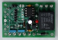
There is no PCB design; the PCB shown on the photo was a left-over from some other project.
Software
The program is written for the B. Knudsen CC5X compiler. An 8 pin PIC12F1840 forms the heart of the circuit. For more information see the comments in the program source.
A number of parameters control the operation of the software:
New PCB
This project can be build on the PCB described: here as the new project photo shows. I added a partslist to summarize which parts have to be used. Compared to the original version I replace Q1 with a BC547b, which is more readily available. The original BS170 can also be used. There is, however, no space on the board for a TO220 mosfet to drive a big speaker.
Connections to the board: X1-X2=immediate loop (1=gnd), X3-X4=delayed loop (3=gnd). JP2=reset key.
The original software can be used without any change. The microcontroller can be programmed on board by connecting a suitable programmer to JP3.
To do
More thorough testing of the installation in practice
Arduino version
Setup of parameters without re-compiling, for instance through USB using an FTD232 and JP3
Most alarm installations for do-it-yourself are wireless nowadays. They are easy to install, but more expensive than a wired installation and every component contains a battery.
This one is wired and therefore a bit more difficult to install, but cheap and simple.
Two inputs are available: one for direct alarm and one with delayed switch-on and delayed alarm.
The latter one is needed to enable you to switch on and off the alarm from inside the building.
Hardware
The circuit is realised with a simple microcontroller. Every alarm loop uses 2 pins of the controller.
The pins are connected to a resistor network and are alternately analog input or digital output (see fig. 1). If A is digital out, a voltage of 0 volt (A low) or approximately 2 volt (A high) can be measured on B, if B is digital out, a voltage of approximately 3 volt (B high) can be measured on A. By going through these steps sequentially a signal as shown on the oscilloscope picture (fig. 2) can be observed. The pulses have a length of 5 ms.
The 15 kohm resistor of the network is placed at the end of the alarm loop and a change of the resistance will generate an alarm. This includes both interrupting and short-circuiting the loop. Therefore normally open and normally closed contacts can be connected to the same loop as shown in the schematic diagram. The 3 voltage levels and the critical resistance make it difficult to disable this alarm circuit. The capacitors C6 and C7 suppress noise from long wires in the alarm loops.
In the schematic shown a relay is connected to the output. Alternatively a loudspeaker can be used. In that case a bigger mosfet must be used (IRFZ34 instead of BS170) and maybe a resistor in series with the speaker to limit the noise. With an 8 ohm speaker a couple of watt can be generated! If a speaker is used parameter OUTPUT in the program is set to 2, 3 or 4 for respectively a buzzer (125 Hz), a tone (750 Hz) or a siren.
ST1 is the connection for the 12V power supply. The current needed is depending on the output load. With a relay 200 mA is sufficient. With a speaker connected 1 or 2 A may be needed. ST2 is the connection for the alarm loops, ST3 for the output. On ST4 a programmer can be connected; if no on-board programming is needed ST4 can be omitted.
There is no PCB design; the PCB shown on the photo was a left-over from some other project.
Software
The program is written for the B. Knudsen CC5X compiler. An 8 pin PIC12F1840 forms the heart of the circuit. For more information see the comments in the program source.
A number of parameters control the operation of the software:
- ALARM_ON: seconds the alarm will sound
- ALARM_OFF: seconds pause after an active alarm (if RESTART==1)
- OUTPUT: there are 5 different modes to control the output 0 and 1 for a relay, 2, 3 and 4 for a speaker.
- STARTDEL: seconds before loop2 activation after switch on (loop 1 is activated immediately)
- LOOP2DEL: seconds before loop2 alarm starts; before this time expires you have to switch off the alarm.
- RESTART: if 0 the program will halt at the end of the alarm time, if 1 the program will restart after the pause time
New PCB
This project can be build on the PCB described: here as the new project photo shows. I added a partslist to summarize which parts have to be used. Compared to the original version I replace Q1 with a BC547b, which is more readily available. The original BS170 can also be used. There is, however, no space on the board for a TO220 mosfet to drive a big speaker.
Connections to the board: X1-X2=immediate loop (1=gnd), X3-X4=delayed loop (3=gnd). JP2=reset key.
The original software can be used without any change. The microcontroller can be programmed on board by connecting a suitable programmer to JP3.
To do
More thorough testing of the installation in practice
Arduino version
Setup of parameters without re-compiling, for instance through USB using an FTD232 and JP3
Diskussion (0 Kommentare)