
Bluetooth musical Tesla Coil
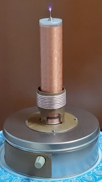
A musical Tesla Coil with Bluetooth streaming from the smartphone! Fully digital, with sigma-delta modulation implemented on an ESP32.
Tesla Coils are old friends of mine… I built my first one, a “regular” one with high voltage transformer and spark gap, when I was 16. In more recent years, I built an analog musical coil and a medium-sized IGBT-based sparker (a DRSSTC, for coilers).
However, I wasn’t satisfied with my first musical coil, so I decided I had to build another. This one is fully digital, with direct streaming of music from a smartphone using Bluetooth, without passing through an analog modulator: in my knowledge, this is quite a new approach.
A video of the result is here: https://youtu.be/RYvuNgtVl88
Short introduction to Tesla Coils
A Tesla Coil is a winding made of many turns of thin magnet wire, wound as a single layer over an insulating tube and well isolated with several layers of varnish. Due to distributed inductance and capacitance, the coil self-resonates on several frequencies (or modes). Normally only the first resonance is used, ranging from tens of kHz for very large coils, to a few MHz for small ones. The frequency also depends on coil terminations: the bottom end is normally grounded, while the top one can be a simple pin, or a so-called “hat”, whose function is increasing capacitance towards ground and hence lowering the resonance frequency.
The coil is normally excited by a “primary” coil made of a small number of turns wound around it at some distance and placed close to the bottom: the two are magnetically coupled and resemble a transformer with high turns ratio, so if the primary is excited by a sinusoidal current with frequency close to the above-mentioned self-resonance, it is possible to obtain high voltages on the secondary. When voltage is sufficiently high (at least a few tens of kV), we get sparks ending in the air. Sparks don’t need to reach ground, because they charge and discharge air molecules in the surrounding of the tip at high frequency.
In most Tesla Coil designs, also the primary is made resonant, with the addition of a capacitor bank. Resonance of the primary makes it become a resistive load (or close to) simplifying the driver. In most cases series resonance is used, so the driver stage sees a small impedance at resonance and can work at a much lower voltage respect to the primary coil (and very much lower respect to the secondary!). An important exception is represented by tube Tesla Coils: in that case high voltage and moderate current are preferred, so parallel resonance is generally adopted.
There are several nice tools on the net to design the coils: my preferred one is JavaTC3D [1].
Large Tesla Coils making huge sparks, from tens of cm to several m, always work in pulsed mode, because the power involved in a single discharge is huge, of the order of tens of kW or more. Several techniques exist for them, from spark gaps to large tubes, to IGBT bridges. A lot of material for them can be found on the net.
For musical coils, on the contrary, it is necessary to work in CW (continuous wave) mode, because the individual sparks of pulsed mode are very noisy. In CW the continuous flow of sparks looks like a flame: if the power driving the primary is amplitude modulated with voice or music, the flame changes of intensity in real time and creates a sound, due to pressure waves produced by the hot plasma. Unfortunately, also CW mode is a bit noisy, because the continuous flow of sparks moves randomly, but this noise looks like a “hiss” and does not disturb too much. The result is fascinating.
Project description
I’ll describe the project starting from the unmodulated CW unit, then explaining how I added modulation. It consists of a square wave generator, a complementary MOS driver and a power stage, as shown in Figure 1 in attachment. The complete schematic and PCB can be found in attachment TeslaMusicale2020.pdf.
Often Tesla Coils work in closed loop, with frequency adjusted by feedback from the coil. In this case it doesn’t: the driving frequency is fixed, although manually adjustable with a potentiometer in order to obtain the best resonance. I initially thought that this approach might have been critical and not viable, but it is not: you can go close to the tip with hands or with a screwdriver and operation remains stable, provided that a sufficiently good earth connection is provided at the base of the coil, the cold side.
The square wave generator can be a lab signal generator when testing resonance and optimizing the resonating cap, but also a device like an ESP32 driven by a suitable software as in my case.
The driver is one of the myriad chips suitable for driving half-bridges. I decided to use the Silabs Si8234, even if I didn’t need galvanic isolation, because I had one spare and because it manages complementary drive, with dead time to avoid cross-conduction, requiring a single input signal. The driver is very powerful, being able to supply 4 A to the gates. With modern, low input capacitance MOSFETs, it can work up to ~1 MHz without overheating. In my case the frequency is around 770 kHz.
For the MOSFETs I chose the FDB3682. These are quite robust parts, rated 100 V, 32 A, 36 mΩ. They are easy to drive, with a maximum gate total charge of 28 nC, that means an average of 21.5 mA at 770 kHz each from the gate power supply: about 0.5 W at 12 V for both. They are so robust that they don’t need large heat sinks, just some copper surface on the PCB.
The resonating cap is a critical component: in this circuit it must withstand up to 10 A peak RF with minimal loss at a capacitance of 7000 pF; peak voltage is around 300 V. Very few parts are suitable for this: the best choice would be probably 1000 V silver mica capacitors, but they are costly and difficult to find. I decided to use SMD paralleled multilayer NP0 1 kV ceramic capacitors from Kemet [2], because according to their data sheet, they have a dissipation factor better than 0.001 up to 1 MHz. This means that 7 units in parallel at 770 kHz, where reactance computes as 29.5 Ω, add an ESR lower than 29.5 mΩ, that at 10 A peak gives less than 1.5 W of combined dissipation, which is within ratings.
I purchased also 470 pF and 100 pF units and I left space for experimentation on the PCB, but resonance proved not critical and, in the end, I left only the 7 units described before.
Also, the DC filter capacitor is delicate: in this case I used a parallel of many (8) 0.1 µF X7R ceramics, followed by a parallel of 2 4.7 µF X5R units, followed by a 1000 µF electrolytic. I optimized the PCB layout so that current peaks are first absorbed by the 0.1 µF, leaving the rest to the others and so avoiding overheating the larger capacitors.
Power supply is in the range 15-25 VDC with 2.5-3.5 A, depending on the number of turns on the primary and on the efficiency of the coils. In my final version, with 8 turns primary, 15 V were more than enough without modulation. With modulation the average power is lower, so I decided to power the circuit at 19 V, using a power supply from an obsolete notebook.
Modulation
Since modulation is digital and is handled by software inside the ESP32, the circuit doesn't change.
As anticipated, audio is added using sigma-delta modulation and this is done in software, with output using the I2S device of the ESP32. This part alone would deserve an entire post… for the moment a short description is included together with the source code, which is stored in [3].
The trick at the base of this modulation scheme is skipping coil drive cycles: an example is shown in attachment sigma-delta-modulation.png. If we "kill" some "ones" every now and then in the square wave, the coil excitation loses drive cycles and hence power. Sigma-delta, in the specific case implemented with a 2nd order modulator, is an intelligent algorithm to optimize the choice of the ones to be killed, trying to maximize the signal to noise ratio.
The coil
The primary coil is 8 turns of 320x0.1 Litz wire. Secondary is 1000 turns of 0.15 mm magnet wire. In attachment there's a file SavedCoil_pri8_0p15.txt, that can be opened inside the great JavaTC3D calculator [1], to see all geometric and electric details.
With this configuration, if large Litz wire isn't used for the primary, losses increase and efficiency drops quite a lot. However, there are many ways to build the coils and certainly other configurations can give even better results.
The PCB includes a bridge between the MOSFETs and the resonating capacitors, allowing to disconnect the two and insert a measurement instrument, e.g. a VNA to characterize and tune the coils before giving power. It also includes a 3-pin header that allows to connect a signal generator or, placing a jumper, use the ESP32.
References
[1] http://www.classictesla.com/java/javatc3d/javatc3d.html
[2] https://uk.rs-online.com/web/p/mlccs-multilayer-ceramic-capacitors/8410773/
[3] https://github.com/rvisent/TeslaCoil_BT.git
Want to build a project?
Bring your design to life with the Elektor PCB Service, powered by Eurocircuits. Upload the project files and order professionally manufactured PCBs or assembled boards through a proven European production platform.
Supporting KiCad, Eagle, Gerber, and ODB++ formats, the service is suitable for everything from prototypes and validation builds to series production and volume manufacturing.
Made in Europe. Fast. Reliable. Professional.
Diskussion (4 Kommentare)