
12V-200V DC-DC Converter for Valve amplifiers
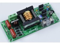
Fairly easy to build DC-DC converter for valve amplifiers using through hole components (just one SO-8 IC). Galvanically isolated high voltage output. The transformer must be created by oneself and its turns ratio sets output voltage. Input voltage is a 5A/ 12VDC AC adapter, output power is 50 W max.
The idea for the circuit is straightforward. It’s primarily designed for the high voltage power supply for valve (tube) amplifiers. The most elementary power supply we can safely create from the mains voltage is made up of a well insulated transformer, (bridge) rectifier and smoothing capacitor. The output voltage depends on the mains voltage, turns ratio, other transformer properties, voltage drop across the diode(s), load and resulting ripple voltage. The size of the ripple depends of course on the size of the smoothing capacitors used for a specific load. Higher capacitance cause higher peak charging currents and a higher voltage drop of the rectified voltage and reduction of the secondary transformer voltage. The high voltage in tube amplifiers is often created this way. Problem is the fixed turn ratio of transformers commercially available, resulting in a supply voltage that can be either to low or to high, although what’s 10 V more or less on 200 V or so... The level of the high voltage (HV) needed for tube amplifiers aside, working with mains voltage is not safe. Touching one terminal of the mains can already be fatal. Another way to create the HV is using a DC AC adapter and use a custom DC-DC converter to convert the lower output voltage to a higher one. This way working with mains voltage can be avoided. The lower DC voltage can also be used for the heaters. Here a 12 VDC AC adapter is used. Downside of the low 12 VDC is high power demands will cause the current needed from the AC adapter to be large. But, modern AC adapters can be very compact, even at higher power ratings since they are primarily switched mode versions.
To make a power supply that’s analogue to the “old fashioned” version with a mains transformer this power supply has no controlling loop, there’s no feedback from output to input. To make the whole design easy to build through hole components are used except for one small IC. It comes in a SO-8 SMD package, making it still easy to solder. This IC is a primary-side push-pull oscillator with dead-time control, the UCC28089. The drivers at the output can sink 1 A and source 0.5 A and are ideal to drive MOSFETs. The absence of a regulating loop in the design means there’s no chance for instability, noise from the PWM control. Duty cycle is set to maximum, or putting it in an other way, dead time is set to an absolute minimum. This makes the rectified secondary output voltage almost DC and only a small smoothing capacitor is necessary. The UCC28089 also has over-current detection. However, the current shutdown threshold is relatively high, 0.725 V typical. Several amperes of current make the power loss in the shunt measuring the current through the MOSFET’s too high and will influence overall efficiency considerably. At 5 A, where we set the limit for this circuit, this would amount to 5 A x 0.725 V = 3.625 watt! The size of the shunt resistor must be large and have a high power rating, at least a 5 W resistor is needed then. At 12 V, 50 W output power and 86 % efficiency, this would amount to 7 % efficiency loss. A way to reduce the loss in the shunt is to use a voltage divider from the supply voltage to add a small voltage to the current sense input. If we add halve of the voltage of the threshold level to we can increase efficiency by more than 3 %. The advantage is also a lower current threshold, should the 12 V supply voltage be higher. Be aware, the maximum power supply voltage for the UCC28089 is 15 V and thus also the maximum supply voltage for this DC-DC converter.
In a push-pull converter energy is directly transferred to the secondary side. In for instance a flyback converter or boost converter energy is first stored in a core, limiting the maximum transferable power for a given core size. In a push-pull converter, when one switch is conducting the other one is turned off and energy is directly transferred. A small time is necessary between swich-over, called dead time, to prevent the primary winding to be shorted. If both switches were to be turned on at the same time the magnetic fields of both primary windings would cancel each other, resulting in an extreme high current, mainly limited by the series resistance of primary windings, MOSFETs, shunt, layout and the 12 V DC power supply. The shunt resistors will probably get damaged or even burn out, and if the short circuit is sustained so will the MOSFETs by getting to hot (even at a little overlap!). To protect the 12 V supply a 5A fuse is placed in series but causes of coarse additional loss. (76 mV at 4.9 A, 0,74 % at 50 W). Advantage of a push-pull converter is the peak current through the switches is only slightly higher than the average load current on the primary side (the current the AC adapter has to provide). Lower peak currents in the switches means less conduction losses and hence results in a higher efficiency of the converter.
The transformer
The most difficult part of the circuit is the transformer. Having to construct a transformer yourself is for many designers a reason not to start a DC-DC converter project. For a first prototype it’s very likely the transformer has to be made by hand by you. To make this part of the design as easy as possible is to use a coil former that’s bigger than strictly needed, the smallest from the ETD series and not for instance a ring core. At 150 kHz the output power can theoretically be more than 170 W, using an ETD29 coil former and N97 material. But in real life there are copper losses. At 12 V input voltage the current flowing would be 16 A (at an optimistic 88 % efficiency), causing 25 W loss for every 0.1ohm. Not very practical. The maximum power transforming a low to high voltage is largely limited by the primary current, so temperature rise in components and even copper tracks etc. No airgap is used in the transformer and reduces the number of turns for primary and secondary winding, making the construction of the transformer even less of an effort. No airgap means higher inductance and better coupling between windings. Because of the size of the coil former the turns are easy to wind. In the prototype 2 windings with each 2 turns and a single secondary winding (37 turns) are used. Also, it’s possible to use the same wire for all windings. The thicker 0,7 mm wire makes it easy wrapping the copper wire around the coil former and keep track of the number of turns. Despite the skin effect, thicker wire also has a higher effective copper area and reduces resistance of the wire (somewhat). Oversizing the transformer, like using thicker wire than needed for a given output power and a larger core, makes the transformer last a long time and most likely the last component to get damaged. However, a larger core means higher core losses. So, if the DC-DC converter is used for low power applications efficiency will be lower. A higher switching frequency will reduce the magnetizing current and increases efficiency at low loads but reduces efficiency at high loads. In both cases however just a few percent. The oscillator frequency of the UCC28089 can be adjusted with a trimmer (P1) from about 200 kHz to 560 kHz. P1 in mid position will be approximately 300 kHz. The switching frequency is halve of the oscillator frequency, so adjustable from 100 kHz to 280 kHz. At 100/150/280 kHz (min/mid/max position of P1) quiescent current of the DC-DC converter is around 300/190/120 mA. At a higher switching frequency the flux density (B) in the core will be lower and so are the losses. But with a higher switching frequency core losses are also higher. However, the relation of the two isn’t linear and it’s best to have a look at the datasheet of the core material (SIFERRIT material N97 from TDK) where the relation relative core losses versus AC field flux density and relative core losses versus frequency are displayed.
So, the idea of the circuit is the turns ratio of the transformer defines the output voltage. Since no transformer is ideal the theoretical turns ratio will not accurately produce the desired output voltage at a specific load. Compared to the high output voltage the voltage drop across the rectifier and filter is minimal. To make alterations of the finished transformer workable, if the deviation of the output voltage is more than expected, it is logical to start construction with the primary windings, insulate them with special tape and insulating sleeves. The secondary winding will then be the winding on the outside and the number of turns can be changed in an early test setup. That is, before a definitive mounting of the transformer to the PCB. Once soldered to the PCB it will be very difficult to remove the transformer without damaging it, like simply cutting the pins to remove it. The rest of the pins can then easily be removed one by one from the pads. For testing first use short thick wires between PCB and transformer to connect it. If everything works fine remove the wires and properly mount the transformer onto the PCB. A disadvantage of producing a high voltage from a low 12 V power supply is the transformation of all series resistances to the secondary side. This relation is the square of the transfer ratio. Copper losses are also related to the square of the current flowing (I2R)
Some basic theory and formula’s
The International System of Units will be used in formula’s. So, Tesla (T) instead of Gauss (Centimetre–gram–second system of units, or CGS) for unit of magnetic flux density B. And in SI there’s also Weber (Wb) as a unit of magnetic flux. A/m is used as a unit for the magnetic field H (magnetizing force) instead of Oersted (Oe). Officially m and m2 are used in the SI system for length and area respectively, but in practice (datasheets) often cm and cm2, like in the CGS system.
1 G = 10-4 T
1 Wb/m2 = 1 T
1 Oe = 1000/4π A/m
1 Wb = 1 T.m2
The circulatory magnetizing force field around a wire:
H = I / 2πr [A/m]
2πr is the circumference at distance r from the wire
The magnetic field density in a vacuum:
B = µ0 * H [T]
µ0 is the vacuum permeability equals 4π×10−7 [H/m] (henry per metre)
Magnetomotive force:
F = N * I = H * l [A, ampere-turn]
l is the length of a solenoid or circumference of a toroid
H is the magnetomotive force per unit length:
H = F / l = (N * I) / l
Applying Ampère's circuital law to a solenoid:
B * l = µ0 * N * I
B = (µ0 * N * I) / l
With core material:
B = (µ0 * µr* N * I) / l
µr is the relative permeability of the core
Magnetic resistance of core material is called reluctance, represented by Rm
F = Φ * Rm
Rm = l / (µ0 * µr* Ac) by definition
where Ac is the cross-section of the core (effective area in datasheets) in cm2 and l is the path length of the flux in the core (effective length in datasheets) in cm
In case of an airgap:
Rm = l / (µ0 * Ac), l is the length of the gap
In a core with an airgap the total reluctance is the sum of both
The inductance of a solenoid is by definition:
L = (N * Φ) / I
From previous equations we can derive the flux in a solenoid with a core
Φ = (µ0 * µr * N * I *Ac) / l = B * A
The induction of a solenoid:
L = (µ0 * µr * N2 *Ac) / l
From this the induction factor AL can be derived. This factor found in datasheets offers an easy way to calculate the inductance of a coil with a core and a given number of turns:
L = N2 * AL
The factor is smaller using a ring core with low permeability when only part of the circumference is used.
Back to the transformer
The induced voltage in a coil:
E = N * (dΦ / dt) Faraday’s law
dΦ = dB * A
Keeping it simple:
E = N * Φ / t
Φ = B * A
E = N * B * A / t
In a push-pull converter the voltage applied to the primary windings are square waves, well almost. In halve of the period the core can be magnetized from Bmax to -Bmax per winding, and vice versa. The other winding does the opposite. Then we get for the time of the magnetization change 2 * Bmax:
t = T/2 = 1 / 2f
The induced voltage:
E = N * 2Bmax * A * 2f
For one of the primary windings we then get following equation:
NP = EP * 104 / (4 * f * Bmax * A)
Area in cm2 (hence the 104)
To calculate the number of turns
N = EP * 104 / (4 * f * Bmax * A)
To make the transformer easy to reproduce, the bobbin chosen is the smallest ETD version which has a larger core than needed for the output power we strive for, 60 W or so (at a theoretically 100 % efficiency). This means the 12 V power supply must be able to deliver 5 A. With no airgap and a high enough switching frequency the number of turns needed for the secondary winding is not to high.
More practical
Specifications from datasheets:
The effective magnetic cross section Ae of an ETD29 is 76 mm2 (76 * 10-6 m2)
The Saturation magnetization BS of N97 material is 410 mT at 100 °C
Core losses at 100 kHz, 25 °C and B = 200 mT, taken from a graph, are 600 kW/m3. So, 600 µW/mm3. The effective volume of a ETD29 core is 5350 mm3. Losses are then 3,21 W. If B is higher losses are also higher, but lower at a higher core temperature. By interpolation losses would be around 2 mW/mm3 at 400 mT. In our case almost 10 W, should the core temperature stay at 25 °C. At 100 °C almost halve (?). But it’s clear, core losses are responsible for a large part of loss in efficiency. Core losses are determent by frequency and magnetization. If the circuit is used for a low power application a higher switching frequency improves efficiency, no-load current is less. For this reason the switching frequency is made adjustable (P1). Something that would pose a problem when this was a regulated power supply, most of them have a fixed frequency with variable pulse width. But then, the latter would increase efficiency at low loads.
While measuring the maximum flux density (saturation) of the core, by increasing pulse duration, showed the maximum for B is reached at around 0.38 T. At 13 µs per winding current clearly starts to increase more than linear. At 13 µs or less the voltage across the shunt is still triangular shaped. In a proof of concept this was measured with 2 primary windings and 3 turns each (for a bit more accuracy), but more like 2 x 2.8 turns. Better would be to test this with more turns. Only 3 turns is more conform the finished transformer. Minimum switching frequency with almost 50 % duty cycle (minimal deadtime) is about 37 kHz (3 turns!). B can be calculated in this test setup and proved to be about 0.38 T. But with so few turns there’s quite an inaccuracy in the calculation:
Bmax ≈ 12 / (4 * 37000 * 2.8 * 76 * 10-6)
The number of turns may be lower if a little non-linear increase in current is accepted and the higher losses that go with it (at a specific switching frequency). At 2 primary turns the minimum switching frequency would be around 52 kHz. But no-load current would be higher.
At 150 kHz and a B of 200 mT the primary number of turns per winding:
N = 12 / (4 * 150000 * 0.2 * 76 * 10-6) = 1.32 and means 2 primary turns. More turns the transformer will need an airgap or else B will become very low. At 100 kHz the result is 1.97 and the transformer can be used at 100 kHz without a problem, and even at lower frequency at a higher B. By using 3 wires in parallel per winding there’s more coverage of the bobbin by the primary windings and less copper loss (skin effect).
Constructing the first transformer, primaries first, secondary on the outside
Two pins of the coil former need to be cut, pin 8 and 10 (according to numbering on the coil former of TDK/Epcos). Look at the PCB layout to make sure you cut the correct pins. Point is, the transformer can be placed one way only. Do this before placing the wires. Primary and secondary pads are well separated on the PCB as are the outputs of the secondary winding on the PCB. Originally there are 13 pins on a coil former of type ETD29, there already is a gap between pins 3 and 4. One output of the secondary winding has two possible connections. Depending on the number of turns and thickness of the copper wire used the number of layers needed can be more than one and the end of the winding is either closer to the opposite side or at the same side as started from. For this reason pins 4, 5, 6 and 9 are connected on the PCB. Pin 7 is the other output of the secondary winding. Always start the secondary winding at pin 7. Pin 1 and 13 are the connections for the first primary winding. Pins 2 and 12 are the connections for the second primary winding. On the PCB names are placed next to the transformer. P1/PC for the first primary winding, P2/PC for the second primary winding. PC stands for common connection of the two primary windings. S1 and S2 are the connections for the secondary winding.
This first transformer was made with copper wire of 0.7 mm for all windings. The two primary windings were placed first and the secondary last. But this leaves little space for the maximum number of turns in a single layer for the secondary. See photos of TR1. Three layers are needed for all secondary turns and explains a higher leakage inductance than the second transformer, reason why the construction of the second transformer is described in more detail, it’s used in the prototype.
Testing the voltage drop at the output with different loads, keeping the 12 V on the input constant (measuring the voltage on the screw terminal K1), gave an approximate output resistance of 132 Ω. Calculating the total primary series resistance resulted in a value of 132/(37/2)2 = 0.386 Ω. The shunt is already 0.15/2 = 0.075 Ω. Leaves about 0.31 Ω caused by the MOSFETs, decoupling capacitors, inductor, fuse, PCB tracks, solder joints and such. Considering all these contributors, the effective series resistance measured/calculated is not that bad. According to the datasheet the ON-resistance of the MOSFETs is 15 mΩ max. (VGS 10 V) and almost negligible. The two MOSFETs are of type TK30A06N1. This type has a very low reverse transfer capacitance of 33 pF and fast switching times (ton/toff 21/28 ns). Additionally the input capacitance of 1050 pF is lower than most other MOSFETs with this low ON-resistance. At maximum power no extra cooling of the transistors is necessary, although constant maximum power is not advised. Of coarse the leakage inductance will have influenced measurements and calculation.
Second transformer, secondary first, primaries on the outside, the preferred one
For a next test a second transformer was made. Starting at pin 7 first 24 turns were wrapped around the coilformer and insulated with tape. Then continued wrapping the second layer with 13 turns to complete the 37 turns in total for the secondary winding. The second connection was insulated with a small piece of PTFE sleeve. Better would have been to also insulate the first connection of the secondary winding also (missing in the photos of TR2). Then the second secondary layer is insulated with tape. Next, the first turn of the first primary winding starts at pin 1. Use a sharp knife to remove enough insulation of every wire and already solder this end before wrapping it around a pin. This makes soldering it to the pin of the coil former go smoothly, but don't solder the wire to the pin yet. Soldering enamelled copper wire produces toxic fumes, so do this in a well ventilated workspace. Stripping the insulation first and then soldering produces a minimum of this fumes. Use a plier to squeeze the wire end tight around the pin before placing two turns around the coil former. Fit the wire, make it (a little more than) long enough, to reach the opposite pin but don’t connect it yet. Do this for the next two turns of this primary winding (three are connected in parallel). Then remove the insulation of the three ends (photo). Solder the ends first and squeeze all three around the pin so the winding is placed optimal (as flat as possible and evenly spread). Do this again for the second primary winding, starting at pin 2. Don’t solder the wires to the pins of the coil former too long, this will melt the plastic of the fixation in the coil former and shift the pin or worse. That’s why the wire ends have to be properly soldered before wrapping them around the pins. Also don’t solder the stripped wire with a too hot soldering iron, the wire otherwise will oxidise very fast and will prevent solder to properly bond with the copper wire.
Measurements were sort a of a surprise, compared to the first transformer. Calculating the secondary resistance from the output voltage drop gave a lower resistance, about 83 ohms: voltage drop is 8.3 V when the load current is increased from 100 to 200 mA. So, the calculated total primary resistance on the PCB is approximately 83/(37/2)2 = 0.243 Ω. It’s probably lower, because of the extra voltage drop caused by the leakage inductance. Efficiency is the same for both transformers, 88 % at 25 W and 86 % at 50 W give or take a percent. So, best guess is the difference in leakage inductance of the transformer is responsible for the different output voltage drops at identical loads. Having the secondary winding on the inside has the preference because of the lower output impedance. But the number of secondary turns depend on the nominal load. At 50 W the output voltage is 200,7 V with a transfer ratio of 37 to 2. Theoretically the output voltage would have to be 222 V (not taking the diodes and filter into account). This discrepancy has to be considered for a different output voltage.
Building the DC-DC converter
First solder IC1 to the PCB, the little SMD (SO-8). To save space the 1 W power resistors (R7-R10) on the primary side are Small Size versions (body 10 mm x 3.5 mm), if you have some old stock or buy random types they might not fit. Look in the BOM for the manufacturers reference of the series we used. Also, C7 should be a Polymer Aluminium type, don’t use an ordinary electrolytic version, it will most likely burn out. The type listed (A750KS227M1EAAE015 from Kemet) can handle a ripple current of 4.42 A at 100 kHz and has a very low series resistance of 15 mΩ (100 kHz/20°C). Mounting the rest of the components is pretty straight forward. The resistor for the led (R11) indicating the presence of the high voltage (HV) must be at least a 350 V type and can be a larger 1 W resistor. Keep in mind, the circuit doesn’t comply with mains Class II specifications! The design of the converter has increased clearances, the copper plane at the output has an increased electrical clearance and also the transformer if properly constructed, and provides an excellent galvanically isolated high output voltage. Of course a lower output voltage is not a problem but the rectifier diodes can be changed to other types (bigger ones) with higher current and lower voltage drop. The pads have 1.3 mm holes. However, current rating of the common mode choke L2 is 1 A and is already the highest in that series.
When using this DC-DC converter make sure that no electrically conducting object are close to components that are connected to the high voltage. The bigger the clearance the better!
The 200V in the title of this project is of course and example. The output voltage can be made higher or lower by changing the number of turns of the secondary, but also by changing the number of turns of the primary windings, if the correct switching frequency is kept in mind! Changing C1 (and R2) for a different oscillator frequency range will change dead time!!! Before changing values, have a good look at the formula’s in the datasheet of the UCC28089.
About core size and maximum output power
This topic seems to be the most difficult part when designing a DC-DC converter using a transformer. If you search the internet a lot of information can be found about calculating transformers, even complete calculators, making itvery easy to design one. But, most sites refrain from calculating core size and refer to pretty much the same kind of table for all kind of different core’s and coil formers such as Exx, EExx, EFxx, EFDxx, EIxx, ETDxx and EERxx. The table’s are usually sorted by maximum power achievable, but switching frequency is often missing. To have an indication how big the core must be a formula using the core area product WaAc (multiplying core cross-section area and window area available for windings) can be used. But factors like topology constant (depends on type of converter), current density (depends on maximum temperature rise permitted) and window utilization factor have to be entered in the formula(s). But it’s not an exact calculation, to many dependencies. Many years ago kit’s for building transformers were available from Block. One kit contained a small roll of insulating film, insulating sleeves, 2 small card boards for a defined airgap, coil former, 2 half cores and 2 clips. Of course copper wire must be obtained elsewhere. Also in the box was a leaflet called ‘Berechnungsbogen für Schaltnetzteil-Űbertrager EB‘, in English: Calculation sheet for switched-mode power supply transformers. It has formula’s for calculating minimum core size, primary and secondary turns, wire diameter for primary and secondary. Core material at that time was N27. Biggest difference with present day N97 is relative core losses are considerable lower for N97, 300 kW/m3 instead of 920 kW/m3 (at 100 kHz/200 mT/100 °C). The formula to calculate then minimum core size:
Minimum core size = 4.7*106 * Maximum total output power / frequency
(mm3 = 4.7*106 * W/Hz)
Using this formula to calculate maximum power at 150 kHz and a core size of 5350 mm3 is 170 W, that’s what I meant with the ETD29 core is bigger than strictly needed.
If anyone knows how to derive the formula or a similar (better) one and/or give insight how to calculate core size more accurately, please share the knowledge.
The PCB in the photo’s of the prototype is version 1.0, a small correction was made in version 1.1, placing the text ‘+HV’ and ‘0’ aside from screw terminal K2.
Some measurements from the prototype
Supply voltage is held constant at exactly 12 V for all loads
Switching frequency 150 kHz
Transformer 1 (2:37, all windings 0.71 mm wire, secondary on the outside)
Load Output voltage
[mA] [V]
0 244
1,3 233.7
5 222
10 218.8
20 216.3
30 214.7
40 213.3
50 211.9
60 210.6
70 209.3
80 208
90 206.6
100 205.3
Transformer 2 (2:37, all windings 0.71 mm wire, primaries on the outside)
[mA] [V]
0 249
1,35 237.6
5 223.2
10 217.9
20 216.2
30 215
40 214
50 213.2
60 212.6
70 211.5
80 210.9
90 210
100 209
200 200.7
Measurements slightly change over time due to temperature rise of components.
Some properties
Supply voltage 9..14 VDC
Maximum output voltage 350 V (higher turns ratio of transformer)
Efficiency (both transformers)
25 W output power 88 %
50 W output power 86 %
Switching frequency
100/150/280 kHz P1 min/mid/max
No load current 12VDC
300/190/120 mA P1 min/mid/max
A high load will prevent the converter to start. This converter was designed for valve amplifiers where the load on the high voltage is very low at power-up!
Bill of material PCB 200307-1 v1.1
Resistor
R1 = 47 kΩ, 600 mW, 1 %, metalfilm, axial
R2 = 1.5 kΩ, 600 mW, 1 %, metalfilm, axial
R3 = 39 kΩ, 600 mW, 1 %, metalfilm, axial
R4 = 1 kΩ, 600 mW, 1 %, metalfilm, axial
R5,R6 = 22 Ω, 600 mW, 1 %, metalfilm, axial
R7,R8 = 0.15 Ω, 1 W, 5 %, wirewound, axial, small size
R9,R10 = 100 Ω, 1 W, 5 %, wirewound, axial, small size
R11 = 220 kΩ, 1 W, 350 V, 5 %, metalfilm, axial
P1 = 100 kΩ, 150 mW, 20 %, 1 turn, trimmer, top adjust
Capacitor
C1 = 150 pF, 100 V, 5 %, C0G/NP0, pitch 5 mm
C2 = 4.7 nF, 50 V, 10 %, X7R, pitch 5 mm
C3,C4,C8 = 1 µF, 50 V, 10 %, X7R, pitch 5 mm
C5,C6 = 220 pF, 100 V, 5 %, C0G/NP0, pitch 5 mm
C7 = 220 µF, 25 V, 20 %, Polymer Aluminum, pitch 3.5 mm, D 8 mm, ESR 15 mΩ,
Kemet A750KS227M1EAAE015
C9,C10 = 470 nF, 400 V, 5 %, Polypropylene, pitch 15 mm (19x9 mm max.)
Inductor/Transformer
TR1 = Core ETD29, N97, Ungapped, TDK/Epcos B66358G0000X197 (2 halves)
TR1 = Coil former, ETD29, B66359W1013T001, TDK/Epcos,*1
TR1 = Clip, B66359S2000X000, TDK/Epcos (2 needed)
L1 = 2.2 µH, 10 %, 5.6 ARMS, 21 mΩ, pitch 5 mm, D 8.5 mm max, Bourns RLB0913-2R2K
L2 = Common Mode Choke 500 µH, 1 A, 0.3 Ω, Kemet SU9V-10005
Semiconductor
D1,D2,D3,D4 = 400 V/1 A, 1.25 V, 30 ns, STTH1R04QRL STMicroelectronics, DO-15,
Maximum size PCB DO-201AD
LED = LED, green, T-1 (3 mm)
T1,T2 = TK30A06N1, TO-220SIS, 60V, 30 A, 15 mΩ
IC1 = UCC28089D, SOIC-8
Other
K1 = 2-way terminal block, pitch 5.08 mm, Phoenix Contact MKDSN 1,5/2-5,08, 13.5A/250V
K2 = 3-way terminal block, pitch 7.68 mm, Phoenix Contact GMKDS 3/2-7,62, 24A/500V
F1 = Cartridge fuse, 5x20 mm, 5 A time delay
F1 = Fuse holder for cartridge fuse 5x20mm, 500V/10A
F1 = Cover for fuse holder
TR1 = Electrical Insulation Tape, Polyester Film, 3M 1350 12 MM
TR1 = Copper wire, 0.71 mm for all windings, 49 turns in total, 3 meter should be enough
TR1 = PTFE protective sleeving, internal diam. 1.02 mm min. , Pro Power STFE 18 CLR, 10 cm
Misc.
PCB 200307-1 v1.1
*1 two pins need to be cut, see text
To make a power supply that’s analogue to the “old fashioned” version with a mains transformer this power supply has no controlling loop, there’s no feedback from output to input. To make the whole design easy to build through hole components are used except for one small IC. It comes in a SO-8 SMD package, making it still easy to solder. This IC is a primary-side push-pull oscillator with dead-time control, the UCC28089. The drivers at the output can sink 1 A and source 0.5 A and are ideal to drive MOSFETs. The absence of a regulating loop in the design means there’s no chance for instability, noise from the PWM control. Duty cycle is set to maximum, or putting it in an other way, dead time is set to an absolute minimum. This makes the rectified secondary output voltage almost DC and only a small smoothing capacitor is necessary. The UCC28089 also has over-current detection. However, the current shutdown threshold is relatively high, 0.725 V typical. Several amperes of current make the power loss in the shunt measuring the current through the MOSFET’s too high and will influence overall efficiency considerably. At 5 A, where we set the limit for this circuit, this would amount to 5 A x 0.725 V = 3.625 watt! The size of the shunt resistor must be large and have a high power rating, at least a 5 W resistor is needed then. At 12 V, 50 W output power and 86 % efficiency, this would amount to 7 % efficiency loss. A way to reduce the loss in the shunt is to use a voltage divider from the supply voltage to add a small voltage to the current sense input. If we add halve of the voltage of the threshold level to we can increase efficiency by more than 3 %. The advantage is also a lower current threshold, should the 12 V supply voltage be higher. Be aware, the maximum power supply voltage for the UCC28089 is 15 V and thus also the maximum supply voltage for this DC-DC converter.
In a push-pull converter energy is directly transferred to the secondary side. In for instance a flyback converter or boost converter energy is first stored in a core, limiting the maximum transferable power for a given core size. In a push-pull converter, when one switch is conducting the other one is turned off and energy is directly transferred. A small time is necessary between swich-over, called dead time, to prevent the primary winding to be shorted. If both switches were to be turned on at the same time the magnetic fields of both primary windings would cancel each other, resulting in an extreme high current, mainly limited by the series resistance of primary windings, MOSFETs, shunt, layout and the 12 V DC power supply. The shunt resistors will probably get damaged or even burn out, and if the short circuit is sustained so will the MOSFETs by getting to hot (even at a little overlap!). To protect the 12 V supply a 5A fuse is placed in series but causes of coarse additional loss. (76 mV at 4.9 A, 0,74 % at 50 W). Advantage of a push-pull converter is the peak current through the switches is only slightly higher than the average load current on the primary side (the current the AC adapter has to provide). Lower peak currents in the switches means less conduction losses and hence results in a higher efficiency of the converter.
The transformer
The most difficult part of the circuit is the transformer. Having to construct a transformer yourself is for many designers a reason not to start a DC-DC converter project. For a first prototype it’s very likely the transformer has to be made by hand by you. To make this part of the design as easy as possible is to use a coil former that’s bigger than strictly needed, the smallest from the ETD series and not for instance a ring core. At 150 kHz the output power can theoretically be more than 170 W, using an ETD29 coil former and N97 material. But in real life there are copper losses. At 12 V input voltage the current flowing would be 16 A (at an optimistic 88 % efficiency), causing 25 W loss for every 0.1ohm. Not very practical. The maximum power transforming a low to high voltage is largely limited by the primary current, so temperature rise in components and even copper tracks etc. No airgap is used in the transformer and reduces the number of turns for primary and secondary winding, making the construction of the transformer even less of an effort. No airgap means higher inductance and better coupling between windings. Because of the size of the coil former the turns are easy to wind. In the prototype 2 windings with each 2 turns and a single secondary winding (37 turns) are used. Also, it’s possible to use the same wire for all windings. The thicker 0,7 mm wire makes it easy wrapping the copper wire around the coil former and keep track of the number of turns. Despite the skin effect, thicker wire also has a higher effective copper area and reduces resistance of the wire (somewhat). Oversizing the transformer, like using thicker wire than needed for a given output power and a larger core, makes the transformer last a long time and most likely the last component to get damaged. However, a larger core means higher core losses. So, if the DC-DC converter is used for low power applications efficiency will be lower. A higher switching frequency will reduce the magnetizing current and increases efficiency at low loads but reduces efficiency at high loads. In both cases however just a few percent. The oscillator frequency of the UCC28089 can be adjusted with a trimmer (P1) from about 200 kHz to 560 kHz. P1 in mid position will be approximately 300 kHz. The switching frequency is halve of the oscillator frequency, so adjustable from 100 kHz to 280 kHz. At 100/150/280 kHz (min/mid/max position of P1) quiescent current of the DC-DC converter is around 300/190/120 mA. At a higher switching frequency the flux density (B) in the core will be lower and so are the losses. But with a higher switching frequency core losses are also higher. However, the relation of the two isn’t linear and it’s best to have a look at the datasheet of the core material (SIFERRIT material N97 from TDK) where the relation relative core losses versus AC field flux density and relative core losses versus frequency are displayed.
So, the idea of the circuit is the turns ratio of the transformer defines the output voltage. Since no transformer is ideal the theoretical turns ratio will not accurately produce the desired output voltage at a specific load. Compared to the high output voltage the voltage drop across the rectifier and filter is minimal. To make alterations of the finished transformer workable, if the deviation of the output voltage is more than expected, it is logical to start construction with the primary windings, insulate them with special tape and insulating sleeves. The secondary winding will then be the winding on the outside and the number of turns can be changed in an early test setup. That is, before a definitive mounting of the transformer to the PCB. Once soldered to the PCB it will be very difficult to remove the transformer without damaging it, like simply cutting the pins to remove it. The rest of the pins can then easily be removed one by one from the pads. For testing first use short thick wires between PCB and transformer to connect it. If everything works fine remove the wires and properly mount the transformer onto the PCB. A disadvantage of producing a high voltage from a low 12 V power supply is the transformation of all series resistances to the secondary side. This relation is the square of the transfer ratio. Copper losses are also related to the square of the current flowing (I2R)
Some basic theory and formula’s
The International System of Units will be used in formula’s. So, Tesla (T) instead of Gauss (Centimetre–gram–second system of units, or CGS) for unit of magnetic flux density B. And in SI there’s also Weber (Wb) as a unit of magnetic flux. A/m is used as a unit for the magnetic field H (magnetizing force) instead of Oersted (Oe). Officially m and m2 are used in the SI system for length and area respectively, but in practice (datasheets) often cm and cm2, like in the CGS system.
1 G = 10-4 T
1 Wb/m2 = 1 T
1 Oe = 1000/4π A/m
1 Wb = 1 T.m2
The circulatory magnetizing force field around a wire:
H = I / 2πr [A/m]
2πr is the circumference at distance r from the wire
The magnetic field density in a vacuum:
B = µ0 * H [T]
µ0 is the vacuum permeability equals 4π×10−7 [H/m] (henry per metre)
Magnetomotive force:
F = N * I = H * l [A, ampere-turn]
l is the length of a solenoid or circumference of a toroid
H is the magnetomotive force per unit length:
H = F / l = (N * I) / l
Applying Ampère's circuital law to a solenoid:
B * l = µ0 * N * I
B = (µ0 * N * I) / l
With core material:
B = (µ0 * µr* N * I) / l
µr is the relative permeability of the core
Magnetic resistance of core material is called reluctance, represented by Rm
F = Φ * Rm
Rm = l / (µ0 * µr* Ac) by definition
where Ac is the cross-section of the core (effective area in datasheets) in cm2 and l is the path length of the flux in the core (effective length in datasheets) in cm
In case of an airgap:
Rm = l / (µ0 * Ac), l is the length of the gap
In a core with an airgap the total reluctance is the sum of both
The inductance of a solenoid is by definition:
L = (N * Φ) / I
From previous equations we can derive the flux in a solenoid with a core
Φ = (µ0 * µr * N * I *Ac) / l = B * A
The induction of a solenoid:
L = (µ0 * µr * N2 *Ac) / l
From this the induction factor AL can be derived. This factor found in datasheets offers an easy way to calculate the inductance of a coil with a core and a given number of turns:
L = N2 * AL
The factor is smaller using a ring core with low permeability when only part of the circumference is used.
Back to the transformer
The induced voltage in a coil:
E = N * (dΦ / dt) Faraday’s law
dΦ = dB * A
Keeping it simple:
E = N * Φ / t
Φ = B * A
E = N * B * A / t
In a push-pull converter the voltage applied to the primary windings are square waves, well almost. In halve of the period the core can be magnetized from Bmax to -Bmax per winding, and vice versa. The other winding does the opposite. Then we get for the time of the magnetization change 2 * Bmax:
t = T/2 = 1 / 2f
The induced voltage:
E = N * 2Bmax * A * 2f
For one of the primary windings we then get following equation:
NP = EP * 104 / (4 * f * Bmax * A)
Area in cm2 (hence the 104)
To calculate the number of turns
N = EP * 104 / (4 * f * Bmax * A)
To make the transformer easy to reproduce, the bobbin chosen is the smallest ETD version which has a larger core than needed for the output power we strive for, 60 W or so (at a theoretically 100 % efficiency). This means the 12 V power supply must be able to deliver 5 A. With no airgap and a high enough switching frequency the number of turns needed for the secondary winding is not to high.
More practical
Specifications from datasheets:
The effective magnetic cross section Ae of an ETD29 is 76 mm2 (76 * 10-6 m2)
The Saturation magnetization BS of N97 material is 410 mT at 100 °C
Core losses at 100 kHz, 25 °C and B = 200 mT, taken from a graph, are 600 kW/m3. So, 600 µW/mm3. The effective volume of a ETD29 core is 5350 mm3. Losses are then 3,21 W. If B is higher losses are also higher, but lower at a higher core temperature. By interpolation losses would be around 2 mW/mm3 at 400 mT. In our case almost 10 W, should the core temperature stay at 25 °C. At 100 °C almost halve (?). But it’s clear, core losses are responsible for a large part of loss in efficiency. Core losses are determent by frequency and magnetization. If the circuit is used for a low power application a higher switching frequency improves efficiency, no-load current is less. For this reason the switching frequency is made adjustable (P1). Something that would pose a problem when this was a regulated power supply, most of them have a fixed frequency with variable pulse width. But then, the latter would increase efficiency at low loads.
While measuring the maximum flux density (saturation) of the core, by increasing pulse duration, showed the maximum for B is reached at around 0.38 T. At 13 µs per winding current clearly starts to increase more than linear. At 13 µs or less the voltage across the shunt is still triangular shaped. In a proof of concept this was measured with 2 primary windings and 3 turns each (for a bit more accuracy), but more like 2 x 2.8 turns. Better would be to test this with more turns. Only 3 turns is more conform the finished transformer. Minimum switching frequency with almost 50 % duty cycle (minimal deadtime) is about 37 kHz (3 turns!). B can be calculated in this test setup and proved to be about 0.38 T. But with so few turns there’s quite an inaccuracy in the calculation:
Bmax ≈ 12 / (4 * 37000 * 2.8 * 76 * 10-6)
The number of turns may be lower if a little non-linear increase in current is accepted and the higher losses that go with it (at a specific switching frequency). At 2 primary turns the minimum switching frequency would be around 52 kHz. But no-load current would be higher.
At 150 kHz and a B of 200 mT the primary number of turns per winding:
N = 12 / (4 * 150000 * 0.2 * 76 * 10-6) = 1.32 and means 2 primary turns. More turns the transformer will need an airgap or else B will become very low. At 100 kHz the result is 1.97 and the transformer can be used at 100 kHz without a problem, and even at lower frequency at a higher B. By using 3 wires in parallel per winding there’s more coverage of the bobbin by the primary windings and less copper loss (skin effect).
Constructing the first transformer, primaries first, secondary on the outside
Two pins of the coil former need to be cut, pin 8 and 10 (according to numbering on the coil former of TDK/Epcos). Look at the PCB layout to make sure you cut the correct pins. Point is, the transformer can be placed one way only. Do this before placing the wires. Primary and secondary pads are well separated on the PCB as are the outputs of the secondary winding on the PCB. Originally there are 13 pins on a coil former of type ETD29, there already is a gap between pins 3 and 4. One output of the secondary winding has two possible connections. Depending on the number of turns and thickness of the copper wire used the number of layers needed can be more than one and the end of the winding is either closer to the opposite side or at the same side as started from. For this reason pins 4, 5, 6 and 9 are connected on the PCB. Pin 7 is the other output of the secondary winding. Always start the secondary winding at pin 7. Pin 1 and 13 are the connections for the first primary winding. Pins 2 and 12 are the connections for the second primary winding. On the PCB names are placed next to the transformer. P1/PC for the first primary winding, P2/PC for the second primary winding. PC stands for common connection of the two primary windings. S1 and S2 are the connections for the secondary winding.
This first transformer was made with copper wire of 0.7 mm for all windings. The two primary windings were placed first and the secondary last. But this leaves little space for the maximum number of turns in a single layer for the secondary. See photos of TR1. Three layers are needed for all secondary turns and explains a higher leakage inductance than the second transformer, reason why the construction of the second transformer is described in more detail, it’s used in the prototype.
Testing the voltage drop at the output with different loads, keeping the 12 V on the input constant (measuring the voltage on the screw terminal K1), gave an approximate output resistance of 132 Ω. Calculating the total primary series resistance resulted in a value of 132/(37/2)2 = 0.386 Ω. The shunt is already 0.15/2 = 0.075 Ω. Leaves about 0.31 Ω caused by the MOSFETs, decoupling capacitors, inductor, fuse, PCB tracks, solder joints and such. Considering all these contributors, the effective series resistance measured/calculated is not that bad. According to the datasheet the ON-resistance of the MOSFETs is 15 mΩ max. (VGS 10 V) and almost negligible. The two MOSFETs are of type TK30A06N1. This type has a very low reverse transfer capacitance of 33 pF and fast switching times (ton/toff 21/28 ns). Additionally the input capacitance of 1050 pF is lower than most other MOSFETs with this low ON-resistance. At maximum power no extra cooling of the transistors is necessary, although constant maximum power is not advised. Of coarse the leakage inductance will have influenced measurements and calculation.
Second transformer, secondary first, primaries on the outside, the preferred one
For a next test a second transformer was made. Starting at pin 7 first 24 turns were wrapped around the coilformer and insulated with tape. Then continued wrapping the second layer with 13 turns to complete the 37 turns in total for the secondary winding. The second connection was insulated with a small piece of PTFE sleeve. Better would have been to also insulate the first connection of the secondary winding also (missing in the photos of TR2). Then the second secondary layer is insulated with tape. Next, the first turn of the first primary winding starts at pin 1. Use a sharp knife to remove enough insulation of every wire and already solder this end before wrapping it around a pin. This makes soldering it to the pin of the coil former go smoothly, but don't solder the wire to the pin yet. Soldering enamelled copper wire produces toxic fumes, so do this in a well ventilated workspace. Stripping the insulation first and then soldering produces a minimum of this fumes. Use a plier to squeeze the wire end tight around the pin before placing two turns around the coil former. Fit the wire, make it (a little more than) long enough, to reach the opposite pin but don’t connect it yet. Do this for the next two turns of this primary winding (three are connected in parallel). Then remove the insulation of the three ends (photo). Solder the ends first and squeeze all three around the pin so the winding is placed optimal (as flat as possible and evenly spread). Do this again for the second primary winding, starting at pin 2. Don’t solder the wires to the pins of the coil former too long, this will melt the plastic of the fixation in the coil former and shift the pin or worse. That’s why the wire ends have to be properly soldered before wrapping them around the pins. Also don’t solder the stripped wire with a too hot soldering iron, the wire otherwise will oxidise very fast and will prevent solder to properly bond with the copper wire.
Measurements were sort a of a surprise, compared to the first transformer. Calculating the secondary resistance from the output voltage drop gave a lower resistance, about 83 ohms: voltage drop is 8.3 V when the load current is increased from 100 to 200 mA. So, the calculated total primary resistance on the PCB is approximately 83/(37/2)2 = 0.243 Ω. It’s probably lower, because of the extra voltage drop caused by the leakage inductance. Efficiency is the same for both transformers, 88 % at 25 W and 86 % at 50 W give or take a percent. So, best guess is the difference in leakage inductance of the transformer is responsible for the different output voltage drops at identical loads. Having the secondary winding on the inside has the preference because of the lower output impedance. But the number of secondary turns depend on the nominal load. At 50 W the output voltage is 200,7 V with a transfer ratio of 37 to 2. Theoretically the output voltage would have to be 222 V (not taking the diodes and filter into account). This discrepancy has to be considered for a different output voltage.
Building the DC-DC converter
First solder IC1 to the PCB, the little SMD (SO-8). To save space the 1 W power resistors (R7-R10) on the primary side are Small Size versions (body 10 mm x 3.5 mm), if you have some old stock or buy random types they might not fit. Look in the BOM for the manufacturers reference of the series we used. Also, C7 should be a Polymer Aluminium type, don’t use an ordinary electrolytic version, it will most likely burn out. The type listed (A750KS227M1EAAE015 from Kemet) can handle a ripple current of 4.42 A at 100 kHz and has a very low series resistance of 15 mΩ (100 kHz/20°C). Mounting the rest of the components is pretty straight forward. The resistor for the led (R11) indicating the presence of the high voltage (HV) must be at least a 350 V type and can be a larger 1 W resistor. Keep in mind, the circuit doesn’t comply with mains Class II specifications! The design of the converter has increased clearances, the copper plane at the output has an increased electrical clearance and also the transformer if properly constructed, and provides an excellent galvanically isolated high output voltage. Of course a lower output voltage is not a problem but the rectifier diodes can be changed to other types (bigger ones) with higher current and lower voltage drop. The pads have 1.3 mm holes. However, current rating of the common mode choke L2 is 1 A and is already the highest in that series.
When using this DC-DC converter make sure that no electrically conducting object are close to components that are connected to the high voltage. The bigger the clearance the better!
The 200V in the title of this project is of course and example. The output voltage can be made higher or lower by changing the number of turns of the secondary, but also by changing the number of turns of the primary windings, if the correct switching frequency is kept in mind! Changing C1 (and R2) for a different oscillator frequency range will change dead time!!! Before changing values, have a good look at the formula’s in the datasheet of the UCC28089.
About core size and maximum output power
This topic seems to be the most difficult part when designing a DC-DC converter using a transformer. If you search the internet a lot of information can be found about calculating transformers, even complete calculators, making itvery easy to design one. But, most sites refrain from calculating core size and refer to pretty much the same kind of table for all kind of different core’s and coil formers such as Exx, EExx, EFxx, EFDxx, EIxx, ETDxx and EERxx. The table’s are usually sorted by maximum power achievable, but switching frequency is often missing. To have an indication how big the core must be a formula using the core area product WaAc (multiplying core cross-section area and window area available for windings) can be used. But factors like topology constant (depends on type of converter), current density (depends on maximum temperature rise permitted) and window utilization factor have to be entered in the formula(s). But it’s not an exact calculation, to many dependencies. Many years ago kit’s for building transformers were available from Block. One kit contained a small roll of insulating film, insulating sleeves, 2 small card boards for a defined airgap, coil former, 2 half cores and 2 clips. Of course copper wire must be obtained elsewhere. Also in the box was a leaflet called ‘Berechnungsbogen für Schaltnetzteil-Űbertrager EB‘, in English: Calculation sheet for switched-mode power supply transformers. It has formula’s for calculating minimum core size, primary and secondary turns, wire diameter for primary and secondary. Core material at that time was N27. Biggest difference with present day N97 is relative core losses are considerable lower for N97, 300 kW/m3 instead of 920 kW/m3 (at 100 kHz/200 mT/100 °C). The formula to calculate then minimum core size:
Minimum core size = 4.7*106 * Maximum total output power / frequency
(mm3 = 4.7*106 * W/Hz)
Using this formula to calculate maximum power at 150 kHz and a core size of 5350 mm3 is 170 W, that’s what I meant with the ETD29 core is bigger than strictly needed.
If anyone knows how to derive the formula or a similar (better) one and/or give insight how to calculate core size more accurately, please share the knowledge.
The PCB in the photo’s of the prototype is version 1.0, a small correction was made in version 1.1, placing the text ‘+HV’ and ‘0’ aside from screw terminal K2.
Some measurements from the prototype
Supply voltage is held constant at exactly 12 V for all loads
Switching frequency 150 kHz
Transformer 1 (2:37, all windings 0.71 mm wire, secondary on the outside)
Load Output voltage
[mA] [V]
0 244
1,3 233.7
5 222
10 218.8
20 216.3
30 214.7
40 213.3
50 211.9
60 210.6
70 209.3
80 208
90 206.6
100 205.3
Transformer 2 (2:37, all windings 0.71 mm wire, primaries on the outside)
[mA] [V]
0 249
1,35 237.6
5 223.2
10 217.9
20 216.2
30 215
40 214
50 213.2
60 212.6
70 211.5
80 210.9
90 210
100 209
200 200.7
Measurements slightly change over time due to temperature rise of components.
Some properties
Supply voltage 9..14 VDC
Maximum output voltage 350 V (higher turns ratio of transformer)
Efficiency (both transformers)
25 W output power 88 %
50 W output power 86 %
Switching frequency
100/150/280 kHz P1 min/mid/max
No load current 12VDC
300/190/120 mA P1 min/mid/max
A high load will prevent the converter to start. This converter was designed for valve amplifiers where the load on the high voltage is very low at power-up!
Bill of material PCB 200307-1 v1.1
Resistor
R1 = 47 kΩ, 600 mW, 1 %, metalfilm, axial
R2 = 1.5 kΩ, 600 mW, 1 %, metalfilm, axial
R3 = 39 kΩ, 600 mW, 1 %, metalfilm, axial
R4 = 1 kΩ, 600 mW, 1 %, metalfilm, axial
R5,R6 = 22 Ω, 600 mW, 1 %, metalfilm, axial
R7,R8 = 0.15 Ω, 1 W, 5 %, wirewound, axial, small size
| MCKNP01SJ015KA10 Multicomp Pro |
| MCKNP01SJ0101A10 Multicomp Pro |
P1 = 100 kΩ, 150 mW, 20 %, 1 turn, trimmer, top adjust
Capacitor
C1 = 150 pF, 100 V, 5 %, C0G/NP0, pitch 5 mm
C2 = 4.7 nF, 50 V, 10 %, X7R, pitch 5 mm
C3,C4,C8 = 1 µF, 50 V, 10 %, X7R, pitch 5 mm
C5,C6 = 220 pF, 100 V, 5 %, C0G/NP0, pitch 5 mm
C7 = 220 µF, 25 V, 20 %, Polymer Aluminum, pitch 3.5 mm, D 8 mm, ESR 15 mΩ,
Kemet A750KS227M1EAAE015
C9,C10 = 470 nF, 400 V, 5 %, Polypropylene, pitch 15 mm (19x9 mm max.)
Inductor/Transformer
TR1 = Core ETD29, N97, Ungapped, TDK/Epcos B66358G0000X197 (2 halves)
TR1 = Coil former, ETD29, B66359W1013T001, TDK/Epcos,*1
TR1 = Clip, B66359S2000X000, TDK/Epcos (2 needed)
L1 = 2.2 µH, 10 %, 5.6 ARMS, 21 mΩ, pitch 5 mm, D 8.5 mm max, Bourns RLB0913-2R2K
L2 = Common Mode Choke 500 µH, 1 A, 0.3 Ω, Kemet SU9V-10005
Semiconductor
D1,D2,D3,D4 = 400 V/1 A, 1.25 V, 30 ns, STTH1R04QRL STMicroelectronics, DO-15,
Maximum size PCB DO-201AD
LED = LED, green, T-1 (3 mm)
T1,T2 = TK30A06N1, TO-220SIS, 60V, 30 A, 15 mΩ
IC1 = UCC28089D, SOIC-8
Other
K1 = 2-way terminal block, pitch 5.08 mm, Phoenix Contact MKDSN 1,5/2-5,08, 13.5A/250V
K2 = 3-way terminal block, pitch 7.68 mm, Phoenix Contact GMKDS 3/2-7,62, 24A/500V
F1 = Cartridge fuse, 5x20 mm, 5 A time delay
F1 = Fuse holder for cartridge fuse 5x20mm, 500V/10A
F1 = Cover for fuse holder
TR1 = Electrical Insulation Tape, Polyester Film, 3M 1350 12 MM
TR1 = Copper wire, 0.71 mm for all windings, 49 turns in total, 3 meter should be enough
TR1 = PTFE protective sleeving, internal diam. 1.02 mm min. , Pro Power STFE 18 CLR, 10 cm
Misc.
PCB 200307-1 v1.1
*1 two pins need to be cut, see text
Want to build a project?
Bring your design to life with the Elektor PCB Service, powered by Eurocircuits. Upload the project files and order professionally manufactured PCBs or assembled boards through a proven European production platform.
Supporting KiCad, Eagle, Gerber, and ODB++ formats, the service is suitable for everything from prototypes and validation builds to series production and volume manufacturing.
Made in Europe. Fast. Reliable. Professional.
Diskussion (10 Kommentare)