
Yet Another Button Cell Charger
Yet another? Well, oké, but then the first question for this proposal is of course: why? Because I am not satisfied with commercial available button cell chargers. Most of them are simple fixed current chargers with a fixed charging time. Buy an other type of rechargeable button cell, and you end up buying another charger.
Yet another? Well, oké, but then the first question for this proposal is of course: why? Because I am not satisfied with commercial available button cell chargers. Most of them are simple fixed current chargers with a fixed charging time. Buy an other type of rechargeable button cell, and you end up buying another charger. If you are able to fix a different type of button cell at all in these chargers, they either undercharge or overcharge the button cell. I now already have about five types of rechargeable button cells in use and I don't want to buy five seperate chargers. I know of one type of charger which supposedly can handle a 3.0V and a 3.6V cell (you have to set a switch on the thing), but reviews on the internet show that 3 out of 4 customers return it as not (proper) functioning.
Furthermore, I have made such a universal one, but it of the “manual” type. It is based on a LM317 with a multiturn potentiometer as current limiter (see photo “old manual charger”). It works fine as long as I constantly keep an eye on the milli-ampere display and on my wristwatch to track the charging time. Because the cell voltage raises during charging, I have to constantly adjust the potentiometer. It is this I want to be automated, so I can do something else, like designing new electronic proposals.
And I think most of the readers of this proposal like to have that also. And like me, they know enough about rechargeable batteries how to correctly charge them in a user unfriendly way. The universal button cell charger will have to let you and me set the parameters and then execute the charging according to our settings, being that in or out the limits of the button cells.
That brings this proposal to the following …
Specifications
First: a universal button cell place holder. Cells with a nominal voltage from 1.2 to 3.6 Volt must be able to be charged. The maximum cell capacity is 180 mAh.
Second: charge current to be set in the range of 1 to 180 mA.
Third: charging time to be set in hours and minutes, ranging form 00:00 to 14:00.
Fourth: setting of a maximum cell voltage, after which some sort of “constant voltage” charging follows.
Fifth: a temperature protecting of the cell which can be set at a level from 20 to 50 degrees celcius.
Sixth: power supply must be 12V dc (to be able to connect it to my “mini-accu”, which is charged by a small solar panel).
Seventh: It will be very hard to realize all this without a microcontroller. That controller should be a ATMEGA328P, the heart of the Arduino UNO.
Eight: if possible the whole proposal is to be realized on a holes- or strips-print, avoiding high costs for a dedicated PCB.
Hardware
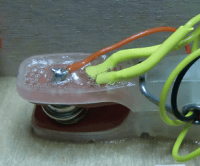
First I discuss the universal button cell placeholder. In my old (“manual”) button cell charger I already solved that problem: a clothespeg is used on which at both arms thumbtacks are driven through. The thumbtack should be of a conducting metal (copper). Connections wires can be easely soldered to them. See the photos “clotchespeg as universal clamp” and “clothespeg detail with ptc” for details of this really universal cell holder. For the temperature sensor I used a ptc in mini-TO92 housing still lying around in a cigarbox with leftover parts. But you might also use some kind of (small) NTC. In that case you should exchange the temperature resistor and R9. I drilled two small holes in the clotchespeg for its terminal wires, covered them with shrink sleeve and fixed all wires with two thick layers of universal glue. All the four wires are led through the metal clamp as a kind of strain relief.
The heart of the charger is a kind of current driver. The ATMEGA328P uses it Arduino I/O 9 as a pulse-width-modulation output for the setpoint to the opamp LT1077. R11 / C11 turn the pulses in a rather smooth dc voltage from 0 to 5 V. The -IN pin of the opamp is connected to a 25 Ohm resistor (actually four 100 Ohm resistors in parallel), which will signal 5 V to the opamp if 200 mA flows through it. The output of the opamp drives the 2N3439 transistor. The transistor has a small cooling ring. Do not think I invented this configuration myself. Look at page 9 of the datasheet for the DAC LTC1451 in “datasheets.zip” for a exact example. I only took it to a 200 mA driver level. But it works perfectly well. People who are really familiar with IC's might even consider to built such a charger around a LM311. It has the same configuration of a opamp and transistor, but in one IC.
The rest of the circuit is straight forward. To measure the voltage on the plus and minus side of the cell, R5 / R6 and R7 / R8 divide these voltages to bring them in ADC range of the microcontroller.
A 7805, three leds, a 16x2 lcd display and the rotary encoder completes it.
Notice I could use a strips print to build the prototype by using an I-board for the ATMEGA328P. More information about the I-board is on this website at http://www.elektor-labs.com/project/i-board-poor-mans-t-board.14256.html. Photo “working prototype” shows the complete workings in a wooden cigarbox.
The power supply may be anything DC of about 12V. In my window I have a small solarpanel, normally used to keep a car battery well when not used for a long time, to slowly charge 10 rechargeable AA batteries, which serve as a mini-accu of 1.8Ah. I added the photos “mini-accu” and “solarpanel” to this proposal to let you see how it is done. But any 12V DC power supply will do.
Software
The complete software for the ATMEGA3128P is designed and tested as a straight forward Arduino Sketch. The source listing is commented for easy reading.
The listing starts with including the LCD driver.
After that follows the definitions of all I/O pins (only A4 and A5 are still free). Then immediately follows the definitions to calculate the various analog and PWM signals from / to engineeringunits (volts, milliamperes, temperature, …).
These values have to be tuned one time at commissioning the charger. Values may be slightly different for each built charger depending on tolerances in resistorvalues, etc.
After that you see a interrupt service routine connected with Timer0. In setup() the timer0 is configured to generate an interrupt every millisecond. From this a 500 millisecond puls is generated which services as blinking signal for the green led and for keeping the charge time up to date. The variables to go with this are declared right before the ISR.
This is followed by two declaration blocks to hold the variables of the settings and the various measurements in engineeringunits.
Then some functions are declared to help to get integer and floating point values in an easy way to the LCD-screen.
Then the two basic functions of a Arduino sketch follow; setup() and loop(). Setup is not very exciting; set Timer0 to CTC mode and value of 250, declare various pins as input, output or PWM (9), set some default values.
Loop() consists of three major parts; first the rotary encoder inputs are checked and from them one-shots are calculated. A one-shot variable (os_ ) is high for one cycle of the loop if a certain condition occurs. They are os_enc_cw (encoder turned one position clockwise), os_enc_ccw (yes, indeed, one position counter clockwise), one-shot encoder pushed and one-shot encoder released.
And the blinksignal also has two one-shots; os_blink_signal_on and os_blink_signal_off.
The first part ends with reading the analog values into voltages, currents and temperature. For the calculation of the temperature look in the “datasheets.zip” for the pdf-file about the ptc.
The real “action” of the program is one big switch statement controlled by the mode variable. In a mode the one-shots or certain conditions bring a new value in the mode variable after which in the next cycle of loop() another part of the “action” or case is executed. The quickest way to understand all the modes and the switchover between them is to look at “User interface schematic” at the Schematics part of this proposal.
At the end of the switch statement some leftover things are programmed, like realizing the blinking text under in the left corner of the LCD screen and the powersaving switchting of the LCD-backlight (shut off after 15 seconds no activity on the rotary encoder).
LEDs
There are three leds to help identify the state the charging process is in.
The green LED blinks during charging and stays constant on when the charging is finished.
The middle led (red) comes on when the charges switches to mode 23 (constant voltage).
And the right red led signals a temperature alarm.
That leaves only some specialities to comment here for a better understanding of the important parts of the software.
61 seconds in a minute. In RUN mode the actual button cell voltage is measured every minute. Actually the cell voltage is always measured, providing the charging current is 1 mA or less. So after every 60 seconds (or more correctly 120 half seconds) the charging is set to 0mA, and the mode is switched to 22. When in this case the half second counter reaches 122, one charging minute is added to the charging time and the charging is resumed at mode 21. Note that the charging time is counting up. This is been done deliberatedly. Because if the charging stops for whatever reason, we know how much time the cell has been charged already, so how “full” it is already. That is easier than to calculate it from the original time set minus the remaining time left.
Constant voltage. Very great chargers recognize when the cell voltage reaches above a certain level and switch over to offer the cell a constant voltage, and watch how the charge current diminishes. When that current reaches some lower limit, the cell is really fully charged and the charging is finished. This Arduino program does something like it, but not exactly. Because its pwm output drives current and not voltage, offering a constant voltage is not possible. What happens instead is that in mode 22, when the cell voltage is measured, the number of minutes that the cell voltage is above the voltage set in the SET mode, is counted. If that number of minutes equals or is greater than the number of minutes set in the #define minutes_high_volt (3 in my version), the charger changes to mode 23. In that mode, the current is lowered 1mA per second as long as the voltage between the plus and minus side of the cell is higher than the high voltage level. If the voltage becomes lower than the set high voltage, the downcounting stops until the cell voltage comes above the set level again. This goes on until the current is lower than 0.05C of the cell (or 1/20 of the original set current or lower than 1 – just to make sure that the charging finishes).
User unfriedly, but … with a little help
Because after implementing the basic functions described here and there being more than enough programming memory unused in the microcontroller, I added the TYP modes.
The charger starts with mode SET, but if you then turn the encoder counterclockwise you enter TYP mode. In here you can scroll with the encoder through some types of rechargable button cells. By pushing enter you confirm your choice and the program then fills the appropriate settings to the SET mode variables. For some button cells, only the long 1/10 capacity charging is available, but when possible, for some cells you are allowed to change that from 1/10 until 1/1 C charging. That will be easier, I think, that constantly looking in your pile of documentation for the datasheet of a particular button cell.
And that will give you now also the oppertunity to add to this project, by suggesting what type of buttoncells should be added to the TYP group.
Diskussion (0 Kommentare)