
Voltage controlled 24dB/oct Synthesizer Filter using LDRs
This 4th order audio filter design is based on four LDRs controlled by one LED. Driving the LED you can control the cutt-off frequency from approximately 20Hz to 20kHz. The damping (Q) can be controlled with a potentiometer up to full oscillation. This simple circuit needs two opamps, can run on a 5V single supply, is easy to build and component cost was around 4 Euro. Demo video shows it working and demonstrates the sound. Sound example files available. A dual supply voltage circuit is also possible
Details on the filter circuit:
Cascading four identical RC circuits without buffers looks like a recepy for a very poor filter with sloppy transition at the cutt-off frequency.
However, the famous Moog ladder filter is actually based on this same cascading. Moog solved the problem in clever way, now also used for this circuit. This is how it works:
A single RC lowpass section is not only a filter but also a frequency dependant phase shifter, starting at zero degree, going to -45 degree exactly at the cuttof frequency and approaching -90 degree beyond that. Now if you have four of these RC's in series you get 4x-45= -180 degree phaseshift only at the cutt-off frequency. Do realise
that -180 degree phaseshift means inverting the sign. Then applying negative feedback from the output to the input of the filter results in positive feedback, giving gainpeaking, but only at the cutt-off frequency. This gives your filter the sharp transistion at cutt-off. By adjusting the amount of negative feedback the gainpeaking can be controlled and at a maximum you get an oscillator.
Details on the LED-LDR concept:
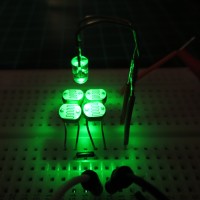
Construction: The LED is mounted hanging some 7mm above the four LDRs (see: led-ldr-setup.jpg). Make sure to shield the circuit from enviromental light because that light will modulate the filter also!
Choice of the LED color: I used LDRs based on CdS, then green or yellow works best. (see: ldr-led-color.gif)
Sensitivity: Measurement showed that the LDR resistance is close to being a linear function of the LED current in the 500kohm to 2kohm resistance range. In total, the LDR resistance could be controlled from 10Mohm to 300 ohm (see ldr-led-current-
graph.gif)
Note: A very high brightness green LED was used here (OVLBG4C7), 0.5uA was enough to have visible light and to start lowering the LDR resistance.
Simulation shows that a roughly exponential control of LED-current can be made for a 0-5V linear control drive voltage by adding only 3 resistors to the LED.
In practice you might need to adjust the resistor values to match your LED.
Details on the opamps:
Use CMOS or JFET opamps because the LDRs will be very high resistors at low frequency setting of the filter.
For the single supply version on +5V I used the MCP602. For dual supply the TL072 could do.
Details on Q-control
-If you turn up the Q to full oscillation, the sinewave amplitude is quite large.
By putting diodes as limiters in parallel to R10 you could lower this
-If you want voltage controlled Q instead of a potmeter you could use another LED-LDR combination for this.
General remarks:
Pro's of this filter:
-The optical control results in a very low control signal leakage compared to most electronic control solutions.
-Can run on single supply 5V making it compatible with microcontrollers (Arduino)
-Handles large signals (several volts) only limited by the opamps.
-Easy to build without needing special components.
Con's of this filter:
-The exponential control curve is not very exact, usually enough for a synth filter but not enough for a musically tuned oscillator.
-LDRs are mentioned to have a fairly slow response, somewhere in the 10-20ms range. I found this to be only true for the decay but the attack measures faster, listen to the fast attack in the demo movie. I measured that the attack can actually be below 1ms as long as the LDR resistance is stepped down to low resistance values.
This results in short attack times being possible for opening the filter at the start of a note. In music applications attack times are usually shorter than decay times so that fits well.
This one and other circuits can also be found on my personal homepage:
www.RS-ELC.nl
Cascading four identical RC circuits without buffers looks like a recepy for a very poor filter with sloppy transition at the cutt-off frequency.
However, the famous Moog ladder filter is actually based on this same cascading. Moog solved the problem in clever way, now also used for this circuit. This is how it works:
A single RC lowpass section is not only a filter but also a frequency dependant phase shifter, starting at zero degree, going to -45 degree exactly at the cuttof frequency and approaching -90 degree beyond that. Now if you have four of these RC's in series you get 4x-45= -180 degree phaseshift only at the cutt-off frequency. Do realise
that -180 degree phaseshift means inverting the sign. Then applying negative feedback from the output to the input of the filter results in positive feedback, giving gainpeaking, but only at the cutt-off frequency. This gives your filter the sharp transistion at cutt-off. By adjusting the amount of negative feedback the gainpeaking can be controlled and at a maximum you get an oscillator.
Details on the LED-LDR concept:
Construction: The LED is mounted hanging some 7mm above the four LDRs (see: led-ldr-setup.jpg). Make sure to shield the circuit from enviromental light because that light will modulate the filter also!
Choice of the LED color: I used LDRs based on CdS, then green or yellow works best. (see: ldr-led-color.gif)
Sensitivity: Measurement showed that the LDR resistance is close to being a linear function of the LED current in the 500kohm to 2kohm resistance range. In total, the LDR resistance could be controlled from 10Mohm to 300 ohm (see ldr-led-current-
graph.gif)
Note: A very high brightness green LED was used here (OVLBG4C7), 0.5uA was enough to have visible light and to start lowering the LDR resistance.
Simulation shows that a roughly exponential control of LED-current can be made for a 0-5V linear control drive voltage by adding only 3 resistors to the LED.
In practice you might need to adjust the resistor values to match your LED.
Details on the opamps:
Use CMOS or JFET opamps because the LDRs will be very high resistors at low frequency setting of the filter.
For the single supply version on +5V I used the MCP602. For dual supply the TL072 could do.
Details on Q-control
-If you turn up the Q to full oscillation, the sinewave amplitude is quite large.
By putting diodes as limiters in parallel to R10 you could lower this
-If you want voltage controlled Q instead of a potmeter you could use another LED-LDR combination for this.
General remarks:
Pro's of this filter:
-The optical control results in a very low control signal leakage compared to most electronic control solutions.
-Can run on single supply 5V making it compatible with microcontrollers (Arduino)
-Handles large signals (several volts) only limited by the opamps.
-Easy to build without needing special components.
Con's of this filter:
-The exponential control curve is not very exact, usually enough for a synth filter but not enough for a musically tuned oscillator.
-LDRs are mentioned to have a fairly slow response, somewhere in the 10-20ms range. I found this to be only true for the decay but the attack measures faster, listen to the fast attack in the demo movie. I measured that the attack can actually be below 1ms as long as the LDR resistance is stepped down to low resistance values.
This results in short attack times being possible for opening the filter at the start of a note. In music applications attack times are usually shorter than decay times so that fits well.
This one and other circuits can also be found on my personal homepage:
www.RS-ELC.nl
Updates vom Autor