
Voice Activated AI Temperature Controller With the MAX78000
This is a voice activated artificial intelligence temperature controller project using the MAX78000FTHR development board. In addition to the development board, the project uses an analog temperature sensor chip, a TFT display, a relay, and an LED. The user enters the required set-point room temperature by speaking. The controller activates/deactivats the relay in order to achieve the desired room temperature. The set-point temperature and the room temperature are both displayed on the TFT. The backgound co
Note: This project is built, tested and is FULLY WORKING.
Project video link: https://www.youtube.com/watch?v=42utVCBr2o4
Temperature Control: Temperature control is very important in many domestic, commercial, and industrial applications. Almost in all industrial chemical plants it is highly important to be able to control the temperature of the chemicals with high degree of accuracy. Temperature control is also used in many domestic devices and applications. For example, the room temperature in a house is usually controlled using a thermostat and a boiler, the temperature of an oven is controlled so that food is cooked at the required temperature, a fridge temperature is controlled so that its contents are at the desired temperature,
Temperature control is normally done using two methods: ON-OFF control and PID based control. ON-OFF control is the easiest method of controlling the temperature. Here, the set temperature is compared to the room temperature whose temperature is to be controlled and a heater is turned ON or OFF to supply temperature to the room so that the desired temperature is achieved. In general, ON-OFF type temperature control can be accurate enough for many domestic and commercial applications. In this project an ON-OFF type controller is used.
The advantages/disadvantages of using ON-OFF type temperature control are:
1. If a relay is used to turn ON/OFF the temperature, then this relay gets worn out in time since it has to operate many many times
2. The control of the temperature is very simple since the model of the plant is not required
3. It is not possible to achieve very accurate continuous temperature control using the ON-OFF method
4. ON-OFF control may produce oscillations in the temperature output which may not be desirable in applications requiring very accurate control of the temperature
The PID (Proportional+Integral+Derivative) is the professional method of controlling the temperature accurately. One disadvantage of this method is that an accurate model of the plant may be required. Also, the PID algorithm is more complex and it is required to derive the P, I, and D parameters of the controller for accurate control. One method is to use the Ziegler-Nicholls algorithm to derive the plant model from a step response and then estimate and then calibrate the P, I, and D parameters of the controller.
The Designed Temperature Controller
---------------------------------------------------
There are many commercially available temperature controller systems available in the market place. This project is based on the concepts of artificial intelligence where a voice activated intelligent temperature controller is designed using the MAX78000FTHR microcontroller development board, At the heart of the MAX78000FTHR is a MAX78000 Cortex-M4 ARM based microcontroller with FPU. Additionally, the board contains 512KB flash memory, 128KB SRAM, 16KB cache, Convolutional Neural Network Accelerator, VGA image sensor, digital microphone, RGB LED, pushbuttons, microSD card adapter, microUSB connector, stereo audio CODEC, SWD debugger, virtual UART port, and many I/O ports.
Block Diagram: Figure 1 shows the block diagram of the project. A 2.4 inch ILI9341 controller based TFT FeatherWing 240x320 pixel touch-screen TFT display is used at the front end of the project to display the user commands, set-point temperature, and teh room temperature. An analog temperature sensor chip, connected to the input of the analog inputs of the MAX78000FTHR is used to read the room temperature. A relay is connected to one of the output ports of the controller, where a mains powered heater can be connected and controlled from this relay. Alternatively, the relay outputs can activate a mains switch (e.g. to control a boiler etc). A small red LED is connected to one of the output ports. The LED is turned ON to indicate when the controller is active.
Circuit Diagram: Figure 2 shows the circuit diagram of the project. LM35 is a 3-pin sensor chip with its output analog voltage directly proportional to the measured ambient temperature. The measured temperature in degrees Celsius is given by T = Vo/10 where Vo is the output voltage in millivolts. For example, at 20 degrees C the output voltage is 200mV, at 30 degrees C it is 300mV and so on. The output pin of the LM35 sensor chip is connected to analog input AIN3 of the MAX78000FTHR, its power and GND pins are connected to +5V and GND of the development board.
The TFT display is connected to the MAX78000FTHR via the SPI bus interface. Pins MISO, MOSI, SCK and CS of the SPI bus are connected to pins P0_6 (MISO), P0_5 (MOSI), P0_7 (SCK), and P0_11 (CS) of the development board. Pin D/C of the TFT display is connected to pin P0_8, and Vcc and GND are connected to +3.3V and GND pins of the MAX78000FTHR.
The Relay operates with +3.3V and is connected to pin P2_6 directly.
A small LED is connected to pin P2_7 through a 470 Ohm current limiting resistor.
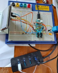
The circuit was built on a breadboard and connections were made using jumper wires. Figure 3 shows the project built on a breadboard.
Power is supplied to the circuit through its mikroUSB cable which should be connected to the USB port of a computer during the program development.
Operation of the project: The operation of the project is shown in Figure 4 as a flow diagram. The following sounds are recognized by the project (invalid spoken commands are rejected by the project):
SHEILA: Attention sound. When this sound is spoken, a prompt will be displayed on the TFT telling
the user that he/she can speak a valid command. You should wait until the prompt is
displayed at the bottom of the screen before saying another command.
ON: Sound to set the set-point temperature. The two numeric sounds following the ON sound set
the set-point temperature. For example, to set the set-point to 23 degrees C, speak the
sound ON TWO THREE followed by YES
YES: Accept the previous command
NO: Reject the previous command
STOP: Stop the controller
Some example sound commands are given below:
Example 1: Suppose that we want to set the room temperature to 23 degrees Centigrade, i.e. the set-point is 23. The following commands must be spoken:
SHEILA ON TWO THREE YES
The TFT display will show both the current room temperature as well as the desired set-point temperature. If the set-point value is greater than the room temperature then the relay as well as the LED will be activated and the TFT background will be RED colour to indicate that the controller is in heating mode. If on the other hand the set-point value is less than the room temperature then the relay will be deactivated (still the LED is ON) and the TFT will display both the set-point and the room temperature on a BLUE background to indicate that the controller is in cooling mode.
Example 2: Suppose that we want to set the room temperature to 23 degrees Centigrade, but by mistake we speak 25. The corrections can be made as follows:
SHEILA ON TWO FIVE NO
SHEILA ON TWO THREE YES
Example 3: Suppose that we wish to stop the controller. The following commands must be spoken (the LED will turn OFF after stopping the controller):
SHEILA STOP
Program listing: The 20 keywords in the supplied Maxim project kws20_demo has been changed to include the word SHEILA. The CNN training program was ran on a Linux Ubuntu operating system after creating a WMware virtual machine on a Windows 10 machine with an i7 CPU, 100GB disk space, and 12GB free memory, without a special GeoForce GPU. After training the new words, the created cnn.c, cnn.h files and the weights.c and weights.h files were copied to the workspace and program main.c under folder kws20_demo was modified for this project. The full main.c program listing is given in Figure 5.
All the project files are collected in a zip file with the name work10.zip (this is an Eclipse Workspace folder) and are attached to this document.
The kws20_demo application supplied by Maxim has been trained to recognize the following 20 words out of a total set of 35 words:
“up, down, left, right, stop, go, yes, no, on, off, one, two, three, four, five, six, seven, eight, nine, zero”
The complete set of 35 words is taken from version 2 of the speech command dataset created by Google (see: Pete Warden, "Speech Commands: A Dataset for Limited-Vocabulary Speech Recognition", Apr. 2018). The dataset consists of over 100k of utterances of 35 different words stored as one-second wave format files sampled at 16kHz:
“backward, bed, bird, cat, dog, down, eight, five, follow, forward, four, go, happy, house, learn, left, marvin, nine, no, off, on, one, right, seven, sheila, six, stop, three, tree, two, up, visual, wow, yes, zero”
For this application, we still trained 20 words from the same set, but replace word go with the word sheila. The 20 words that we will be training are therefore as follows:
“up, down, left, right, stop, sheila yes, no, on, off, one, two, three, four, five, six, seven, eight, nine, zero”
Function Detected_Word detects the spoken word and returns an integer number which is used to identify the detected sound. Number 100 is returned if a non-valid sound is detected by the program. The temperature control cycle is entered everytime the program goes round its loop.
Function Controller basically implements an ON/OFF type temperature control task. The controller has two modes: heating mode and cooling mode. Here, the ambient room temperature is read from the sensor chip and it is compared to the desired set-point value. The relay is then activated/deactivated depending on the output of this comparison. If set-point > room temperature then the controller is in heating mode and the relay is activated. If on the other hand, set-point < room temperature then the controller is in cooling mode and the relay is deactivated. The LED is kept ON while the controller is active. The LED is turned OFF and the controller action is disabled after the SHEILA STOP commands are spoken..
The ELEKTOR logo was converted into a bitmap image and then into a c file, and is displayed when the project is started. After this logo a heading is displayed for several seconds. The user is then ready to enter spoken commands. Some typical displays are shown in Figures 6.1 to Figure 6.7 as follows:
Figure 6.1 Displaying the Elektor logo at startup
Figure 6.2 Displaying the short heading
Figure 6.3 Prompt to say SHEILA before speaking a command
Figure 6.4 Command to set the desired set-point temperature
Figure 6.5 Set point is lower than room temperature (cooling mode) - BLUE screen
Figure 6.6 Set point is higher than room temperature (heating mode) - RED screen
Figure 6.7 Shutdown display
Example run of the project: An example run of the project is shown in the video link: https://photos.app.goo.gl/N3g4a9Eg3EVuY3uA8 or at: https://www.youtube.com/watch?v=42utVCBr2o4. Notice that the ELEKTOR logo is displayed when power is applied to the project, or when the Reset button is pressed. Then, a short screen is displayed which gives some information about the project. The user is then prompted to speak valid commands, mainly by speaking the desired set-point temperature value.
Suggestions for future work: This temperature controller project developed by the author can be improved by the following modifications/additions:
Project video link: https://www.youtube.com/watch?v=42utVCBr2o4
References
https://datasheets.maximintegrated.com/en/ds/MAX78000.pdf
https://www.maximintegrated.com/en/design/technical-documents/app-notes/7/7417.html
https://www.maximintegrated.com/en/design/videos.html/vd_1_rtp4xipe#popupmodal
https://datasheets.maximintegrated.com/en/ds/MAX78000FTHR.pdf
https://www.maximintegrated.com/content/dam/files/design/tools/ev-kits/schematics/max78000-fthr-schematic.pdf
Project video link: https://www.youtube.com/watch?v=42utVCBr2o4
Temperature Control: Temperature control is very important in many domestic, commercial, and industrial applications. Almost in all industrial chemical plants it is highly important to be able to control the temperature of the chemicals with high degree of accuracy. Temperature control is also used in many domestic devices and applications. For example, the room temperature in a house is usually controlled using a thermostat and a boiler, the temperature of an oven is controlled so that food is cooked at the required temperature, a fridge temperature is controlled so that its contents are at the desired temperature,
Temperature control is normally done using two methods: ON-OFF control and PID based control. ON-OFF control is the easiest method of controlling the temperature. Here, the set temperature is compared to the room temperature whose temperature is to be controlled and a heater is turned ON or OFF to supply temperature to the room so that the desired temperature is achieved. In general, ON-OFF type temperature control can be accurate enough for many domestic and commercial applications. In this project an ON-OFF type controller is used.
The advantages/disadvantages of using ON-OFF type temperature control are:
1. If a relay is used to turn ON/OFF the temperature, then this relay gets worn out in time since it has to operate many many times
2. The control of the temperature is very simple since the model of the plant is not required
3. It is not possible to achieve very accurate continuous temperature control using the ON-OFF method
4. ON-OFF control may produce oscillations in the temperature output which may not be desirable in applications requiring very accurate control of the temperature
The PID (Proportional+Integral+Derivative) is the professional method of controlling the temperature accurately. One disadvantage of this method is that an accurate model of the plant may be required. Also, the PID algorithm is more complex and it is required to derive the P, I, and D parameters of the controller for accurate control. One method is to use the Ziegler-Nicholls algorithm to derive the plant model from a step response and then estimate and then calibrate the P, I, and D parameters of the controller.
The Designed Temperature Controller
---------------------------------------------------
There are many commercially available temperature controller systems available in the market place. This project is based on the concepts of artificial intelligence where a voice activated intelligent temperature controller is designed using the MAX78000FTHR microcontroller development board, At the heart of the MAX78000FTHR is a MAX78000 Cortex-M4 ARM based microcontroller with FPU. Additionally, the board contains 512KB flash memory, 128KB SRAM, 16KB cache, Convolutional Neural Network Accelerator, VGA image sensor, digital microphone, RGB LED, pushbuttons, microSD card adapter, microUSB connector, stereo audio CODEC, SWD debugger, virtual UART port, and many I/O ports.
Block Diagram: Figure 1 shows the block diagram of the project. A 2.4 inch ILI9341 controller based TFT FeatherWing 240x320 pixel touch-screen TFT display is used at the front end of the project to display the user commands, set-point temperature, and teh room temperature. An analog temperature sensor chip, connected to the input of the analog inputs of the MAX78000FTHR is used to read the room temperature. A relay is connected to one of the output ports of the controller, where a mains powered heater can be connected and controlled from this relay. Alternatively, the relay outputs can activate a mains switch (e.g. to control a boiler etc). A small red LED is connected to one of the output ports. The LED is turned ON to indicate when the controller is active.
Circuit Diagram: Figure 2 shows the circuit diagram of the project. LM35 is a 3-pin sensor chip with its output analog voltage directly proportional to the measured ambient temperature. The measured temperature in degrees Celsius is given by T = Vo/10 where Vo is the output voltage in millivolts. For example, at 20 degrees C the output voltage is 200mV, at 30 degrees C it is 300mV and so on. The output pin of the LM35 sensor chip is connected to analog input AIN3 of the MAX78000FTHR, its power and GND pins are connected to +5V and GND of the development board.
The TFT display is connected to the MAX78000FTHR via the SPI bus interface. Pins MISO, MOSI, SCK and CS of the SPI bus are connected to pins P0_6 (MISO), P0_5 (MOSI), P0_7 (SCK), and P0_11 (CS) of the development board. Pin D/C of the TFT display is connected to pin P0_8, and Vcc and GND are connected to +3.3V and GND pins of the MAX78000FTHR.
The Relay operates with +3.3V and is connected to pin P2_6 directly.
A small LED is connected to pin P2_7 through a 470 Ohm current limiting resistor.
The circuit was built on a breadboard and connections were made using jumper wires. Figure 3 shows the project built on a breadboard.
Power is supplied to the circuit through its mikroUSB cable which should be connected to the USB port of a computer during the program development.
Operation of the project: The operation of the project is shown in Figure 4 as a flow diagram. The following sounds are recognized by the project (invalid spoken commands are rejected by the project):
SHEILA: Attention sound. When this sound is spoken, a prompt will be displayed on the TFT telling
the user that he/she can speak a valid command. You should wait until the prompt is
displayed at the bottom of the screen before saying another command.
ON: Sound to set the set-point temperature. The two numeric sounds following the ON sound set
the set-point temperature. For example, to set the set-point to 23 degrees C, speak the
sound ON TWO THREE followed by YES
YES: Accept the previous command
NO: Reject the previous command
STOP: Stop the controller
Some example sound commands are given below:
Example 1: Suppose that we want to set the room temperature to 23 degrees Centigrade, i.e. the set-point is 23. The following commands must be spoken:
SHEILA ON TWO THREE YES
The TFT display will show both the current room temperature as well as the desired set-point temperature. If the set-point value is greater than the room temperature then the relay as well as the LED will be activated and the TFT background will be RED colour to indicate that the controller is in heating mode. If on the other hand the set-point value is less than the room temperature then the relay will be deactivated (still the LED is ON) and the TFT will display both the set-point and the room temperature on a BLUE background to indicate that the controller is in cooling mode.
Example 2: Suppose that we want to set the room temperature to 23 degrees Centigrade, but by mistake we speak 25. The corrections can be made as follows:
SHEILA ON TWO FIVE NO
SHEILA ON TWO THREE YES
Example 3: Suppose that we wish to stop the controller. The following commands must be spoken (the LED will turn OFF after stopping the controller):
SHEILA STOP
Program listing: The 20 keywords in the supplied Maxim project kws20_demo has been changed to include the word SHEILA. The CNN training program was ran on a Linux Ubuntu operating system after creating a WMware virtual machine on a Windows 10 machine with an i7 CPU, 100GB disk space, and 12GB free memory, without a special GeoForce GPU. After training the new words, the created cnn.c, cnn.h files and the weights.c and weights.h files were copied to the workspace and program main.c under folder kws20_demo was modified for this project. The full main.c program listing is given in Figure 5.
All the project files are collected in a zip file with the name work10.zip (this is an Eclipse Workspace folder) and are attached to this document.
The kws20_demo application supplied by Maxim has been trained to recognize the following 20 words out of a total set of 35 words:
“up, down, left, right, stop, go, yes, no, on, off, one, two, three, four, five, six, seven, eight, nine, zero”
The complete set of 35 words is taken from version 2 of the speech command dataset created by Google (see: Pete Warden, "Speech Commands: A Dataset for Limited-Vocabulary Speech Recognition", Apr. 2018). The dataset consists of over 100k of utterances of 35 different words stored as one-second wave format files sampled at 16kHz:
“backward, bed, bird, cat, dog, down, eight, five, follow, forward, four, go, happy, house, learn, left, marvin, nine, no, off, on, one, right, seven, sheila, six, stop, three, tree, two, up, visual, wow, yes, zero”
For this application, we still trained 20 words from the same set, but replace word go with the word sheila. The 20 words that we will be training are therefore as follows:
“up, down, left, right, stop, sheila yes, no, on, off, one, two, three, four, five, six, seven, eight, nine, zero”
Function Detected_Word detects the spoken word and returns an integer number which is used to identify the detected sound. Number 100 is returned if a non-valid sound is detected by the program. The temperature control cycle is entered everytime the program goes round its loop.
Function Controller basically implements an ON/OFF type temperature control task. The controller has two modes: heating mode and cooling mode. Here, the ambient room temperature is read from the sensor chip and it is compared to the desired set-point value. The relay is then activated/deactivated depending on the output of this comparison. If set-point > room temperature then the controller is in heating mode and the relay is activated. If on the other hand, set-point < room temperature then the controller is in cooling mode and the relay is deactivated. The LED is kept ON while the controller is active. The LED is turned OFF and the controller action is disabled after the SHEILA STOP commands are spoken..
The ELEKTOR logo was converted into a bitmap image and then into a c file, and is displayed when the project is started. After this logo a heading is displayed for several seconds. The user is then ready to enter spoken commands. Some typical displays are shown in Figures 6.1 to Figure 6.7 as follows:
Figure 6.1 Displaying the Elektor logo at startup
Figure 6.2 Displaying the short heading
Figure 6.3 Prompt to say SHEILA before speaking a command
Figure 6.4 Command to set the desired set-point temperature
Figure 6.5 Set point is lower than room temperature (cooling mode) - BLUE screen
Figure 6.6 Set point is higher than room temperature (heating mode) - RED screen
Figure 6.7 Shutdown display
Example run of the project: An example run of the project is shown in the video link: https://photos.app.goo.gl/N3g4a9Eg3EVuY3uA8 or at: https://www.youtube.com/watch?v=42utVCBr2o4. Notice that the ELEKTOR logo is displayed when power is applied to the project, or when the Reset button is pressed. Then, a short screen is displayed which gives some information about the project. The user is then prompted to speak valid commands, mainly by speaking the desired set-point temperature value.
Suggestions for future work: This temperature controller project developed by the author can be improved by the following modifications/additions:
- In this project the simple ON/OFF type controller is used. This may be OK when used at home. It will be more accurate and also more professional to use the PID (Proportional+Integral+Derivative) algorithm to control the temperature
- The LM35 temperature sensor chip is not very accurate. It may be preferable to use a digital temperature sensor, such as the DSB1820 or TMP102. Digital ones are less prone to external noise and they usually have better accuracies and better reliabilities
- Although the selected words are enough to set the desired temperature and start and stop the controller, it may be more user friendly if more spoken words are added to the project.
- Voice output can be attached to the project so that for example alarm conditions (e.g. if the room temperature gets above a certain upper point) .can be spoken on a speaker.
Project video link: https://www.youtube.com/watch?v=42utVCBr2o4
References
https://datasheets.maximintegrated.com/en/ds/MAX78000.pdf
https://www.maximintegrated.com/en/design/technical-documents/app-notes/7/7417.html
https://www.maximintegrated.com/en/design/videos.html/vd_1_rtp4xipe#popupmodal
https://datasheets.maximintegrated.com/en/ds/MAX78000FTHR.pdf
https://www.maximintegrated.com/content/dam/files/design/tools/ev-kits/schematics/max78000-fthr-schematic.pdf
Diskussion (1 Kommentar)