
Super Servo Tester Rev 2
This SuperServoTester based on the RP-PICO is much faster than the version with ATMega328. Its operation is identical. This achievement was the subject of an article in the Elektor magazine for the month of January 2022 (May-June 2023 for the English version).
SuperServoTester 2nd issue
(English translation from French thanks to Reverso, french version below)
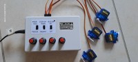
In 2022, I developed the SuperServoTester based on the ATMega328. Its function is to test 4 servos at a time, but especially to test a quadcopter mixer. Five operating modes are possible, from simple servo test to mixer test. This achievement was the subject of an article in the Elektor magazine for the month of January 2022 (May-June 2023 for the English version). It is also present on the site [1].
A reader who performed this edit was disappointed that this first edit did not work very well in automatic mode : during use, the servos indeed have a jerky movement, which is not satisfactory.
I have acquired from Raspberry PI-PICO modules that are much faster than the ATMega328. The PI-PICO can be clocked at 300 MHz, almost 20 times faster than the ATMega328! For a test device of this type, the clock frequency is important.
The operating principle is unchanged: 2 operating modes, Manual or Auto, 2 display modes, Stack or Square, and Buzzer On or Off.
- In Manual mode, this tester must be powered by an external power supply.
- In Auto mode, it must be powered by the model’s power supply; this power supply must not exceed 5.5 Volts.
So I resumed the general principle of this realization, but using the Raspberry PI-PICO module. This of course required some adaptations:
- - The PI-PICO ports only accept 3.3 V input: this involves adapting the incoming signals using level shifters.
- - The PI-PICO has only 3 ADC ports available, whereas it is necessary to measure the voltages from the 4 potentiometers used in manual mode. So I added an ADC module based on the ADS1115 chip. Monitoring of the circuit’s supply voltage is performed by one of the PI-PICO’s ADC ports. The ADC module and the SH1106 display are controlled by the default I2C port GP4 and GP5.
The PI-PICO is very fast, and much higher than the ATMega328 in number of ports and especially in FlashRom: but here the important criterion is the clock frequency: when programming, select the highest clock speed, is 300 MHz. The software occupies very little FLashRom and RAM.
I chose a more readable OLED screen because it’s bigger, the SH1106, as well as the corresponding Adafruit library. This library required to adapt the display routines.
The I2C port does not have pull-up resistors: they are already integrated into the ADC module and the OLED display.
In AUTO mode, the voltage coming from the receiver must not exceed 5.5 Volts, which is the maximum voltage supported by the RT6150 regulator of the PI-PICO module; in this mode, the current consumed is 80 mA. Furthermore, it is important to keep in mind that the RT6150 can supply 800 mA at most. During tests with 4 servos, ensure that the consumption does not exceed this value.
This new version of the software is developed with the Arduino IDE, and downloaded via the USB port of the PI-PICO module. Select the CPU speed of 300 MHz (overclocking) before uploading.
SuperServoTester 2ème version
Olivier CROISET
En 2022, j’ai développé le SuperServoTester à base de l’ATMega328. Sa fonction est de tester 4 servos à la fois, mais surtout de tester un mélangeur de quadcopter. Cinq modes de fonctionnement sont possibles, du simple test de servo au test de mélangeur. Cette réalisation a fait l’objet d’un article dans le magazine Elektor du mois de janvier 2022 (Mai-Juin 2023 pour la version en anglais). Il est également présent sur le site [1].
Un lecteur qui a réalisé ce montage a été déçu que ce premier montage ne fonctionnait pas très bien en mode automatique : lors de l’utilisation, les servos ont, en effet, un mouvement saccadé, ce qui n’est pas satisfaisant.
J’ai acquis depuis des modules Raspberry PI-PICO qui sont bien plus rapide que l’ATMega328. Le PI-PICO peut être cadencé à 300 MHz, soit presque 20 fois plus rapide que l’ATMega328 ! Pour un appareil de test de ce type, la fréquence d’horloge est importante.
Le principe de fonctionnement est inchangé : 2 modes de fonctionnement, Manual ou Auto, 2 modes d’affichage, Stack ou Square, et Buzzer On ou Off.
- En mode Manual, ce testeur doit être alimenté par une alimentation externe.
- En mode Auto, il doit être alimenté par l’alimentation du modèle ; cette alimentation ne doit pas excéder 5.5 Volts.
J’ai donc repris le principe général de cette réalisation, mais en utilisant le module Raspberry PI-PICO. Cela a bien sûr nécessité quelques adaptations :
- Les ports du PI-PICO n’accepte en entrée que du 3.3 V : ceci implique d’adapter les signaux entrants à l’aide de level-shifters.
- Le PI-PICO n’a que 3 ports ADC disponibles, alors qu’il faut mesurer les tensions issues des 4 potentiomètres utilisés en mode manuel. J’ai donc ajouté un module ADC à base de la puce ADS1115. La surveillance de la tension d’alimentation du circuit est réalisée par un des ports ADC du PI-PICO. Le module ADC et l’afficheur SH1106 sont commandés par le port I2C par défaut GP4 et GP5.
Le PI-PICO est très rapide, et bien supérieur à l’ATMega328 en nombre de ports et surtout en FlashRom : mais ici, le critère important est la fréquence d’horloge : lors de la programmation, sélectionner la vitesse d’horloge la plus élevée, soit 300 MHz. Le logiciel n’occupe que très peu de FLashRom et de RAM.
J’ai choisi un écran OLED plus lisible car plus grand, le SH1106, ainsi que la librairie Adafruit correspondante. Cette librairie a nécessité d’adapter les routines d’affichage.
Le port I2C ne comporte pas de résistances de pull-up : celles-ci sont déjà intégrées aux module ADC et à l’afficheur OLED.
En mode AUTO, la tension venant du récepteur ne doit pas dépasser 5.5 Volts, qui est la tension maximale supportée par le régulateur RT6150 du module PI-PICO ; dans ce mode, le courant consommé est de 80 mA. De plus, il est important de garder à l’esprit que le RT6150 peut fournir 800 mA au maximum. Lors d’essais avec 4 servos, veiller à ce que la consommation ne dépasse pas cette valeur.
Cette nouvelle version du logiciel est développée avec l’IDE Arduino, et téléchargé par le port USB du module PI-PICO. Sélectionner la vitesse de CPU de 300 MHz (overclocking) avant la programmation.
BOM
A1 : Module RP-PICO
U1 : Module ADC1115 : (à base de ADS1115)
U2 : Afficheur : OLED SH1106
U3 : Module Level-shifter
U4 : Régulateur 7805 TO220
Q1 : BC548
D1 : LED jaune
D2 : 1N4001
C1, C2, C5 : 100 uF 16 V
C3 : 100 nF
C4 : 2000 uF 25 V
R1 : 10 k Ohm
R2 : 47 k Ohm
R3 : 22 k Ohm
R4 : 47 Ohm
RV1, RV2, RV3, RV4 : 10 k
BZ1 : Buzzer 5Vcc
SW1, SW2, SW3 : interrupteurs 2 voies, 2 positions
J1, J2, J3, J4, J5, J6, J7, J8 : Connecteurs de servos, 3 voies
J9 : Connecteur barrel jack
Coffret plastique : 125 x 80 x 32 mm environ
Diskussion (3 Kommentare)