
Small audio mixer
With a simple design, it will provide you with quite a few services
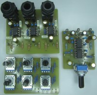
Version A (ALPS Potentiometers)
The project consists of 2 PCBs:
The inputs, levels, Pan Pots, as well as the L&R Bus are located on the first board which initially can accommodate 8 signals but can be cut according to individual needs. In my case, it’s a 3x2 mixer for monitoring.
Channel 1 is the sound pickup microphone, channel 2 is a GSM return and channel 3 is an auxiliary return. All this is of course preceded by adequate preamps. In1, In2, In3 are obviously at line level.
The second board provides the mixing and output stage function.
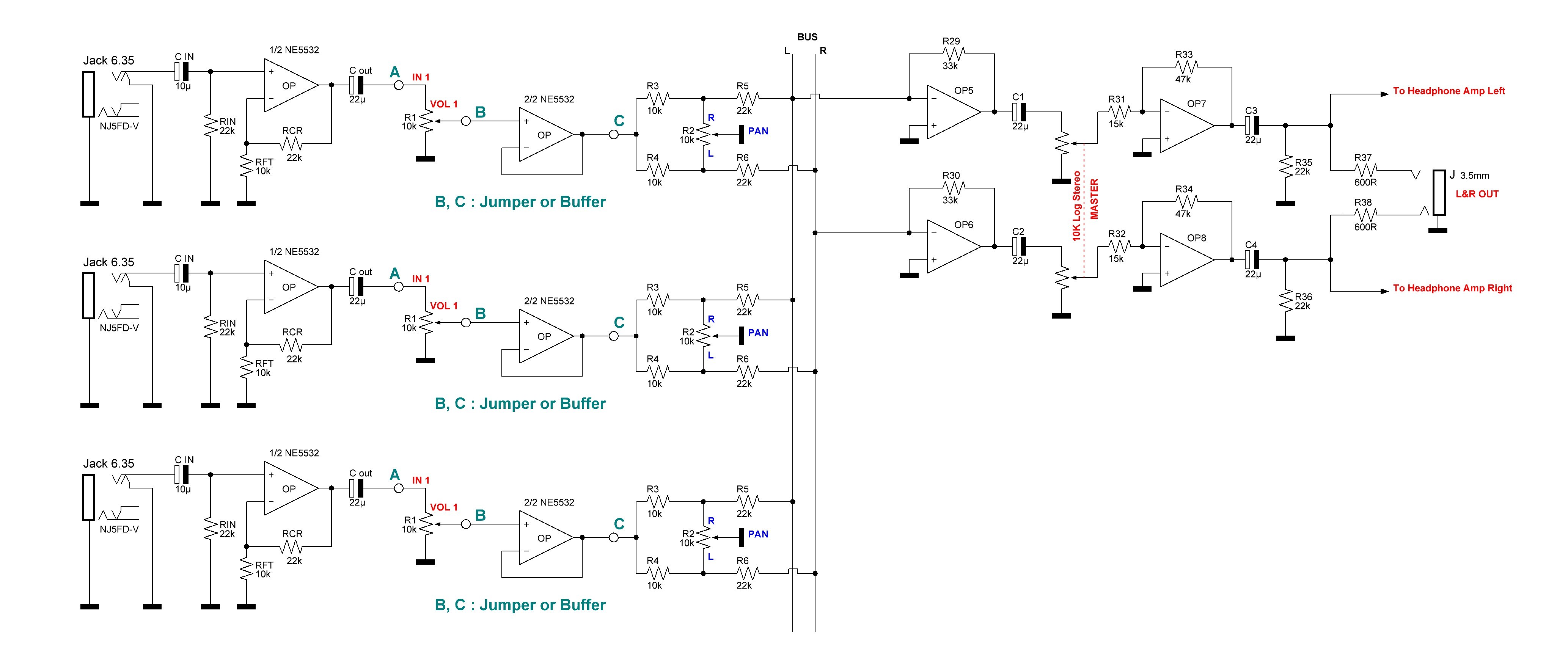
At the schematic level, we are really in simplicity.
R1, R7, R13 adjust the input dosages.
R2, R8, R14 assumes the function of Pan Pot to assign in stereo space. For my project, I chose models with a central notch.
Here is another assembly with virtual masses for the Pan Pot. To send to the right, junction R3, R5 is grounded so nothing to the left. Same when junction R4, R6 is grounded nothing on the right.
OP1 & OP2 are in summing mode. A potentiometer adjusts the output level followed by a stage (OP3, OP4) which provides a gain of 10 dB.
Here is the reference for ALPS potentiometers :
The project consists of 2 PCBs:
The inputs, levels, Pan Pots, as well as the L&R Bus are located on the first board which initially can accommodate 8 signals but can be cut according to individual needs. In my case, it’s a 3x2 mixer for monitoring.
Channel 1 is the sound pickup microphone, channel 2 is a GSM return and channel 3 is an auxiliary return. All this is of course preceded by adequate preamps. In1, In2, In3 are obviously at line level.
The second board provides the mixing and output stage function.
At the schematic level, we are really in simplicity.
R1, R7, R13 adjust the input dosages.
R2, R8, R14 assumes the function of Pan Pot to assign in stereo space. For my project, I chose models with a central notch.
Here is another assembly with virtual masses for the Pan Pot. To send to the right, junction R3, R5 is grounded so nothing to the left. Same when junction R4, R6 is grounded nothing on the right.
OP1 & OP2 are in summing mode. A potentiometer adjusts the output level followed by a stage (OP3, OP4) which provides a gain of 10 dB.
Here is the reference for ALPS potentiometers :
RK09L1140A5E Vertical 10K log (Track Level )
RK09L114001T Vertical 10K Lin with center detent ( Pan Pot )
RK09712200MC Horizontal Stéréo 10K log ( Master )
Version B (BOURNS Potentiometers)
The diagrams & PCB having been modified, it is an increased version with possibilities of an input stage.
As soon as possible I will publish all these changes
Here is the reference for BOURNS potentiometers :
PTV111-3415A-A103 Vertical 10K log (Track Level )
PTV111-3220A-B103 Vertical 10K Lin with center detent ( Pan Pot )
PTV112-1417A-A103 Horizontal Stéréo 10K log ( Master )
Updates des Autors