
Raindrop lights for Christmas
I always liked the Christmas “snowfall” or “raindrop” lights. (O.K., I know it is Easter and not Christmas, but I never managed to finish a Christmas project on-time!
- I always liked the Christmas “snowfall” or “raindrop” lights. (O.K., I know it is Easter and not Christmas, but I never managed to finish a Christmas project on-time! – Sorry, Easter has passed too, so I’m getting ready for next Christmas!!!).
- There are many circuits in the Internet that produce this effect with the use of a simple microcontroller. Most of them use some kind of multiplexing of the outputs. However, I decided to make a circuit without a microcontroller! So, no code, no programming, no programmers, just a soldering iron! (Do I sound like Steve Ciarcia ?)
- The circuit consists of two parts: One part is a 16-bit serial-in/parallel-out shift register formed by two (2) cascaded 74HC595 chips. Each output of the shift register drives one led.
- The other part of the circuit generates the pulses that drive the clock and serial-in inputs of the shift-register. There are two version of the circuit: a simple one and a “PWM-like”.
- Simple version: A timing circuit (555 as a multivibrator) generates a square pulse that drives the clock inputs of the 74HC595. Note that the 74HC595 has the shift register plus an output storage register: when both registers are driven by the same clock signal, the output is delayed by one clock period. (Schematic in figure 1)
- Another timing circuit generates the shift register’s input data. It has to have a frequency slightly greater than 16-times the frequency of the clock signal (the grater the difference, the faster the drop falls). The “on” time of this signal determines the length of the drop. In order to have a good control of the “on” time, I decided to produce this signal using two (2) 555 circuits: the first one works as a multivibrator where the user controls its frequency. The second one works as a “one-shot” that is trigger by the former, so the user can control the length of the pulse. (Schematic in figure 2, timing in figure 3)
- “PWM-like” version: Here, the shift register’s clock works much faster than the simple version. One pulse every 16 is produced to drive the clock of the output register. This extra signal is produced by a 74163 4-bit counter. The same circuit as the one in the simple version can be used to drive the shift register’s data input (this can be a good test to see if the circuit works fine up to this point). Just replace the three 1uf capacitors with 10nf capacitors (100 times faster!).
- The enhancement consists of modulating the signal produced by the “one-shot” timer, leading to a series of pulses with increasing (or decreasing) width. This produces the effect of a drop that is brighter in one of its ends! A counter with some resistors on its output is used to modulate the “one-shot” timer. (Schematic in figure 4, timing in figures 5 and 6).
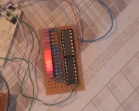
- Some photos and videos are provided in the respective files.
- Note_A: In my prototype I used TTLs for the counters (74LS163), so all the unused inputs are assumed to be in “high” state. If you use CMOS versions, make sure to connect these inputs to Vcc.
- Note_B: In my prototype I used many components that just happened to be in my desk. For example I used red leds instead of white ones! I also had only 14 of them instead of 16! I have mixed CMOS (74HC595) with TTL (74LS163) logic, but is seems to work O.K.!
- Note_C: The values of the resistors that control the PWM have not the best values, some experiments are required. However, even with these values, the PWM effect looks better in real life than in my video.
- Note_D: In the “PWM” mode, the adjustment of the 555s requires some time: the leds may run to the opposite position, the result may look like a “wave” instead of a drop, and so on. You have to find the correct point of the variable resistors. In my working example, all trimmers are set about in their middle position. The produced pulses have periods of 3.85ms and 0.233ms (note that 3.85 = 16.5 X 0.233, which means that the slow clock is a little slower than 16-times that faster clock!)
- Note_E: The R-C network between the two 555 can be removed if one adjusts the “off”-time of the driving timer to be less than the “on” time of the single-shot 555.
Diskussion (0 Kommentare)