
Quick & dirty nickel battery conditioner.
The circuit presented here is of proven worth with Ni-Cd batteries, but theresults are a little less impressive with Ni-Mh batteries.
The circuit presented here is of proven worth with Ni-Cd batteries, but the
results are a little less impressive with Ni-Mh batteries. Neverleless, it
can breathe some new life into metal-hydride batteries that have started
performing less well than they used to.
The author has a small and dwindling supply of AA Ni-Cd cells that are needed for an application with intermittent high current draw. Some consideration was given to converting a salvaged SMPSU into a pulse charger, this would work stunningly well with Ni-Cd cells but previous experiments with Ni-Mh cells gave disappointing results - in any case modifying an off line switcher is pretty tricky and possibly dangerous (even if a suitable candidate can be aquired).
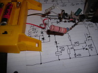
The basis for this project was the iron-cored mains transformer salvaged from an old "dumb" Ni-Cd charger. The transformer in question has a 7.5-0-7.5 centre tapped secondary and used a 2 diode FW rectifier to feed a row of current limiting resistors that charged up to 4 cells side by side. To keep the
circuit as simple as possible, a bridge rectifier was used to rectify the
full 15V available from the secondary and charge/condition the cells in
series. The prototype was rigged for 3x AA in series but it should handle 4
without any component changes, 2 cells could be accomodated but it would be
advisable to increase the 39R 3W current limiting resistor to 56R.
The clever bit of conditioning nickel cells, is to feed them mostly charge
current, but interspersed with sharp pulses of discharge current. Apparently
this shakes up the internal chemistry while the cell is charging, one
description given online suggests that the electrode materials form smaller
granules and thus exhibit higher energy density.
The circuit has been kept to the bare minimum, it would have been possible
to diode-OR multiple MOSFETs from the KSP2222A collector, but you will also need a battery holder that allows each cell to be wired independently in
isolation from the others, this will also require separate charge current
limiter and MOSFET current limiter resistors for each channel, the resistors
will also have to be increased and/or a lower secondary voltage used.
The narrow discharge pulses are carried by the MOSFET, in the prototype this
was a surface mount type salvaged from a scrap motherboard, ratings of 70A & 20 or 30V are fairly usual, if this resource is not available an IRF540 can
do the job - but may need a small heatsink. The MOSFET is driven by the
KSP2222A which serves as a zero crossing detector and inverter, everytime
the rectified half-cycles dip to zero there is breifly no bias to keep the
transistor saturated, at which point the MOSFET conducts for a narrow
discharge pulse, an additional rectified supply - this time smoothed, feeds
a voltage via the 2k2 resistor to pull the MOSFET gate up when the
transistor is off. The 47uF reservoir on the gate supply has a 1k bleed
resistor to quickly discharge it, otherwise with a power outage and no bias
supply to saturate the transistor, the MOSFET would stay conducting and
overheat the MOSFET limiting resistor with current from the battery. All of
the diodes shown do a job and are important, the 1N4004 at the top of the
schematic for example, prevents the battery voltage from interfering with
the zero-crossing waveform or feeding the gate supply rail during power
outages.
The KSP2222A is a manufacturers designation for the PN2222A, which is the
TO92 plastic version of the 2N2222A in a TO18 metal can, a BC337 would do or possibly the Japanese 2SC1815. The common 2SC945 and BC547 are other possibilities, but less powerful than the types previously mentioned and
could run a bit warm.
Diskussion (0 Kommentare)