
Pulsar DDS Function Generator with ATMega328
Code for the Pulsar DDS Function Generator using ATMega328, including several improvements to the functionality and display.
Pulsar DDS Function Generator with ATMega328
I have written code for the Pulsar DDSFG using the ATMega328 microprocessor, and have made a number of modifications to the display and functionality which readers might find useful.
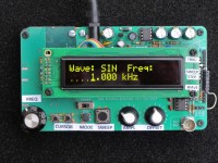
I have replaced the LCD display with a 2x20 character OLED display which I had left from an old defunct project as I much prefer OLED displays for clarity and brightness. Obviously this is optional, and my code can easily be modified for the original LCD.
There are three versions of the code:
DDSFG_Atmega328_v1: This gives the same functions and display as the original.
DDSFG_Atmega328_v2: This includes enhancements to functionality and display.
DDSFG_Atmega328_v3: This version requires three additional button switches, which further improve usability.
Code files were written on the Arduino IDE.
There are some essential modifications that need to be made to the board for all versions. See the schematic1.jpg and schematic2.jpg files
On IC U9 (4053)
Bend pins 6 (INH) and 14 (SQ) so that they do not connect to socket.
Connect pin 6 to net T, J3 pin 7.
Leave pin 14 not connected.
Connect pin 9 (SQW) to net SQ, J3 pin 13.
On IC U7 (Atmega):
In my code the INH signal is pin PD3, because PC6 is the programming reset, which can only be an input.
The OLED requires a signal for pin RW; this is connected to PD1 (formerly TX).
Functional changes in version 2
Exit from sweep mode by pressing the Mode button.
On exit from sweep mode, the frequency is reset to 1 kHz.
Sweep mode has option to manually step forwards or backwards through the sweep frequencies (Step Through mode). The rotary encoder performs the move.
In sweep mode, the time per step can be selected as well as steps per decade.
The approximate total sweep time is also displayed (very approximate for total sweep time less than about 10 secs).
All latest sweep settings are saved for next entry to sweep mode.
There are two output trigger pulses, one for start of sweep and one for each step in the sweep.
Display changes in version 2
Frequency is displayed in Hz, kHz or MHz.
Leading spaces marker is one pixel instead of underscore.
When setting up sweep mode, the new time per step option is displayed, the number of steps per decade is shown, and approx total sweep time is also displayed when the time per step is being selected.
In Step Through mode, the frequency of each step is displayed. Also in Sweep mode, if time per step is 0.5sec or more, the frequency of each step is displayed.
Additional changes in version 3
I have added a dedicated button for setting sweep and step-through mode.
I have added two buttons to move cursor left or right -- when pressed briefly the cursor moves one position.
When right button is pressed and held, all digits right of cursor are set to zero. When left button is pressed and held, all digits left of cursor are cleared.
The pullups for cursor buttons are implemented in the code.
Version 3 also has a “display saver”, since I believe OLED displays are prone to image burn-in. If the rotary encoder is not touched for about 15 mins, the display is replaced by a dim moving block character. Movement of the rotary encoder restores display.
To accommodate the extra buttons, and also allow for larger display, I have extended the board on left edge with a piece of scrap PCB. The extra connections are just wires on the underside. I’ve also moved the rotary encoder to left edge, as I think this is makes it more user-friendly.
Three observations
Finally, I am no expert in writing code, and am sure it could it could be much improved. it has not been rigorously tested, so might have errors I have not found; my apologies in advance for any shortcomings. Also, having modified the board for version 3, I cannot readily go back to version 2, so two code changes for v3 that were also meant to be in v2 have in fact not been implemented: Display of frequency when sweeping, and display saver. There might be others? It is not difficult to edit v2 to include above, but I have not done so because I cannot test the changes.
All relevent files are attached. The three Arduino code files have been renamed to type txt so that they are accepted. They need to be changed to type ino and placed in a directory with same name.
I have written code for the Pulsar DDSFG using the ATMega328 microprocessor, and have made a number of modifications to the display and functionality which readers might find useful.
I have replaced the LCD display with a 2x20 character OLED display which I had left from an old defunct project as I much prefer OLED displays for clarity and brightness. Obviously this is optional, and my code can easily be modified for the original LCD.
There are three versions of the code:
DDSFG_Atmega328_v1: This gives the same functions and display as the original.
DDSFG_Atmega328_v2: This includes enhancements to functionality and display.
DDSFG_Atmega328_v3: This version requires three additional button switches, which further improve usability.
Code files were written on the Arduino IDE.
There are some essential modifications that need to be made to the board for all versions. See the schematic1.jpg and schematic2.jpg files
On IC U9 (4053)
Bend pins 6 (INH) and 14 (SQ) so that they do not connect to socket.
Connect pin 6 to net T, J3 pin 7.
Leave pin 14 not connected.
Connect pin 9 (SQW) to net SQ, J3 pin 13.
On IC U7 (Atmega):
In my code the INH signal is pin PD3, because PC6 is the programming reset, which can only be an input.
The OLED requires a signal for pin RW; this is connected to PD1 (formerly TX).
Functional changes in version 2
Exit from sweep mode by pressing the Mode button.
On exit from sweep mode, the frequency is reset to 1 kHz.
Sweep mode has option to manually step forwards or backwards through the sweep frequencies (Step Through mode). The rotary encoder performs the move.
In sweep mode, the time per step can be selected as well as steps per decade.
The approximate total sweep time is also displayed (very approximate for total sweep time less than about 10 secs).
All latest sweep settings are saved for next entry to sweep mode.
There are two output trigger pulses, one for start of sweep and one for each step in the sweep.
Display changes in version 2
Frequency is displayed in Hz, kHz or MHz.
Leading spaces marker is one pixel instead of underscore.
When setting up sweep mode, the new time per step option is displayed, the number of steps per decade is shown, and approx total sweep time is also displayed when the time per step is being selected.
In Step Through mode, the frequency of each step is displayed. Also in Sweep mode, if time per step is 0.5sec or more, the frequency of each step is displayed.
Additional changes in version 3
I have added a dedicated button for setting sweep and step-through mode.
I have added two buttons to move cursor left or right -- when pressed briefly the cursor moves one position.
When right button is pressed and held, all digits right of cursor are set to zero. When left button is pressed and held, all digits left of cursor are cleared.
The pullups for cursor buttons are implemented in the code.
Version 3 also has a “display saver”, since I believe OLED displays are prone to image burn-in. If the rotary encoder is not touched for about 15 mins, the display is replaced by a dim moving block character. Movement of the rotary encoder restores display.
To accommodate the extra buttons, and also allow for larger display, I have extended the board on left edge with a piece of scrap PCB. The extra connections are just wires on the underside. I’ve also moved the rotary encoder to left edge, as I think this is makes it more user-friendly.
Three observations
- The first two power blocks I tried produced significant 100Hz ripple on the output.Third one I tried is good, no ripple.So you need to check and make sure you have a good enough supply.
- When set to SIN mode, I initially observed quite large noise spikes on the output.If you set frequency at about 50kHz and reduce amplitude to about 200mVpp, you can see very obvious interference spike coinciding with the trigger square wave edges.My first guess was that the U9 device (4053 mux) might be the culprit, so I tried removing it, but spikes were still present. (Incidentally, the sole purpose of U9 is to provide the square wave output).I then removed the CR_OPBITEN command in the code for writing to the AD9834 when in SIN mode, so that the SBIT_OUT is disabled.This fixed the problem; output is now very clean.Drawback is that there is now no trigger output.At present I have no other ideas on how to fix this.So for now you have a choice:Clean output but no trigger signal, or trigger signal but slightly degraded output.In TRI mode there is no problem with spikes because for some reason SBIT_OUT cannot be enabled and so a trigger pulse is never available.
- The AD9834 is clocked at 100MHz (pin MCLK) even though the datasheet headline states that it is a 75MHz device.It would seem that this design gets away with “overclocking” ?
Finally, I am no expert in writing code, and am sure it could it could be much improved. it has not been rigorously tested, so might have errors I have not found; my apologies in advance for any shortcomings. Also, having modified the board for version 3, I cannot readily go back to version 2, so two code changes for v3 that were also meant to be in v2 have in fact not been implemented: Display of frequency when sweeping, and display saver. There might be others? It is not difficult to edit v2 to include above, but I have not done so because I cannot test the changes.
All relevent files are attached. The three Arduino code files have been renamed to type txt so that they are accepted. They need to be changed to type ino and placed in a directory with same name.
Want to build a project?
Bring your design to life with the Elektor PCB Service, powered by Eurocircuits. Upload the project files and order professionally manufactured PCBs or assembled boards through a proven European production platform.
Supporting KiCad, Eagle, Gerber, and ODB++ formats, the service is suitable for everything from prototypes and validation builds to series production and volume manufacturing.
Made in Europe. Fast. Reliable. Professional.
Updates des Autors