
Propulsion module kit for mobile robotics
- Abstract
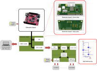
This article proposes an electronic platform dedicated to any mobile robotics applciation. This platform uses an existing microcontroller board , the powerful A13-Olinuxino board (https://www.olimex.com/Products/OLinuXino/A13/) from Olimex running Linux, but any microcontroller suporting UART, I2C and SPI are also compatible. Concretely, we propose two extending boards whom electrical architecture is depicted in the main project picture :
- an extension board that extends the possibilities of the motherboard
- a motor board with all the necessary devices to control two propulsion motors.
These boards highlights the modular approach developped in our robotic projects (www.quimesis.be).
- The Extension board
The Olinuxino provices a 10-header with three communication buses (I2C, SPI and serial buses) and a GND-3.3V supply. The extension board is connected to that header and :
- Add a Controller Area Network (CAN) interface to communicate with industrial sensors and devices. The CAN bus is a must in automotive applications thanks to its high reliability and real-time operation. Its broadcast messages allow to easily extend the bus with other devices.
- The MCP I/O's are optional and can be connected to some Olinuxino GPIO to optimize the CAN communication.
- Keep the I2C bus available (and add pull up resistors on it).
- Add an USB to serial connection (via a FT232R) for making available a debug connection between the Olinuxino board and a computer.
- The Motor board
In order to use the Olinuxino in a mobile robotics application, we propose a second board, using the CAN communication to instantiate a communication between the Olinuxino Board and a STM32 microcontroller. This microcontroller controls two ‘H’-bridges The Motor board contains the essential for a mobile robotics application :
- A cheap STM32 72MHz ARM-Cortex-M3 microcontroller, ideal for automotive applications with CAN interface and quadrature encoder inputs connected to the CAN bus via a CAN transceiver, and powered by the Olinuxino board trough the Extension board. The STM32 allows to free the Olinuxino board from the motors control. The Olinuxino board can therefore handle the main AI decisions and informations coming from its own GPIO (from sensors, …).
- An USB to serial connection (via a FT232R) in order to program the STM32 using its internal bootloader. (There is therefore no need for a JTAG connector.)
- Two A4950 bridges in order to drive two DC motors and entries for two encoders in quadrature. Bridges and signals from encoders are independently powered and optocally decoupled with the rest of the circuit
- Somes GPIO’s.
For simple applications, the motor board can be used standalone, where both control loops and high-level intelligence application run on the STM32. STM32 firmware and Olinuxino package will be provided for the full project. Follow-up articles could cover specific software configurations.
- Anti latch-up tip
The A4950 is really easy to use, but if these entries are set to 5V before the electronic inside the A4950 is turn on, a latch-up occurs and burns the A4950. In order to avoid that, we used a simple circuit to create the 5V powering the entries of the A4950. This circuit is enlighted in the schematic annexed to this proposal. When the power is turned on (from 0 to 24V), the 15V Zener ensures that the 5V only appears when the power is between 20V and 24V. As the electronic inside the A4950 is turned on when the power voltage is at 7V, the latch-up is avoided. Diode1 D ensures that the 5V fastly drop to 0 to avoid a latch at the turn off.
Diskussion (0 Kommentare)