Programming the Arduino in BASIC - Using I2C Part. 3
The I2C bus with GCBasic
Programming the Arduino in BASIC - Using I2C - Part. 3
The I2C (Inter-Integrated Circuit) bus is a synchronous serial communication protocol that allows multiple electronic components (sensors, displays, memories, etc.) to be connected within the same system.
Without going into detail here about how it works (which is widely documented elsewhere), this section covers the basics of I2C programming in GCBasic, applied to three devices that are widely used on Arduino: the pcf8574 port expander, the I2C LCD display, and the DS1307 RTC module (the RTC module will be covered in a future publication).
GCBasic offers two modes for managing the I2C bus: -Software mode : via I2C commands, allowing any pins to be used. -Hardware mode : via HI2C commands, using the I2C module integrated into the microcontroller.
The choice depends on the hardware: If the microcontroller (e.g., PIC16Fxxx) does not have a hardware module, software mode must be used. If the microcontroller has a hardware module (TWI on AVRs, MSSP on PICs), hardware mode is preferable for better performance and more reliable management.
The Arduino UNO's I2C in GCBasic mode
The Arduino UNO board is equipped with an ATMega328p. This microcontroller has a TWI hardware module for I2C. We will therefore use HI2C commands. The SDA line is available on port PC4. The SCL line is available on port PC5.
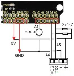
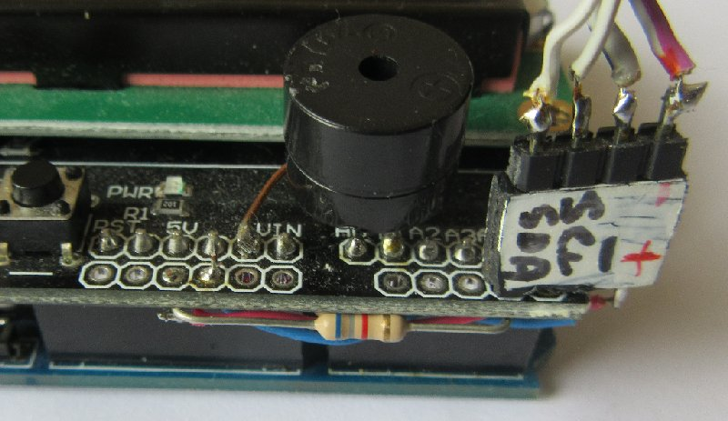
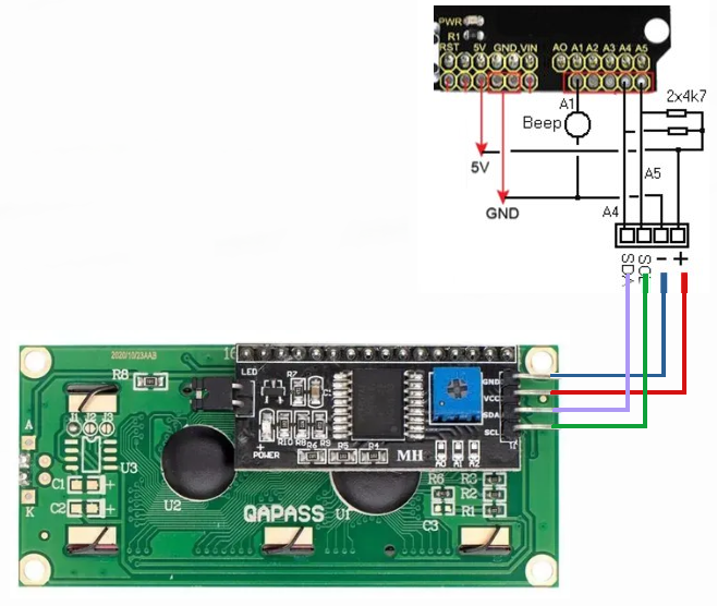
I installed a connector on the LCD Shield board :
Test the I2C bus and find out the device numbers on the LCD
If you have started programming the Arduino with parts 1 and 2 of my projects. I suggest you move straight on to programming an I2C sniffer. Connect an I2C module to be tested to the LCD Keypad shield connector. Test the Scanner_i2c_LCD.gcb program. Implementing I2C is very simple. It includes: - the TWI module declaration (using HI2C commands), - details of the pins used, - Master operating mode.
;Definition I2C avec module TWI #define HI2C_BAUD_RATE 400 #define HI2C_DATA PORTC.4 #define HI2C_CLOCK PORTC.5 ;Pins I2C Dir HI2C_DATA in ; SDA en in Dir HI2C_CLOCK in ; SCL en in ;Periph I2C mode MASTER HI2CMode Master
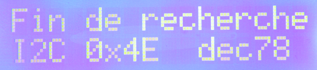
The program then tests all possible addresses from 0 to 255. The Acknowledge (ACK) test checks that a slave device responds to the I2C address sent by the master. After flashing the Arduino, the display 0x4E appears on the LCD shield, so this is the address to use. This address corresponds to the pcf8574 circuits with bits A0, A1, and A2 set to 1. Note: This very simple program is limited and only handles a single I2C device.
Test the I2C bus and find out the device numbers on Terminal
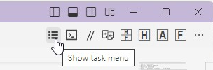
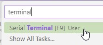
The I2C sniffer on the terminal is more comprehensive (Scanner_i2c_rs232). It allows you to specify different addresses in cases where there are several devices on the I2C bus. GCBasic has a very handy terminal for viewing information using the USB bus. Request Show task menu > Serial Terminal
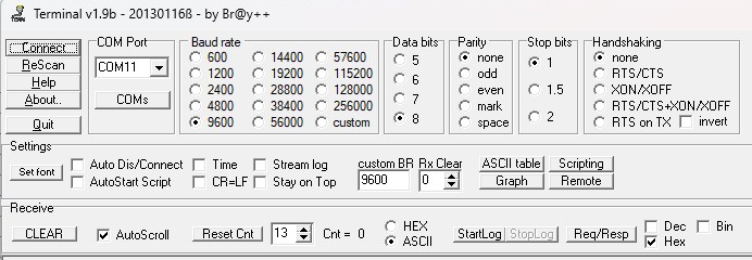
Select the Arduino's COM port, a baud rate of 9600, and Connect :
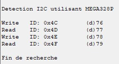
In this example, two I2C devices are detected: one at address 0x4C and the other at 0x4E. These values correspond to the 8-bit addresses (Write mode) used by GCBasic. Each I2C device actually has two consecutive addresses when expressed in 8 bits: - one for Write mode — R/W bit = 0 - one for Read mode — R/W bit = 1 In standard I2C, slave addresses are encoded on 7 bits (from 0x00 to 0x7F, or 0 to 127 in decimal). The detection program scans all values from 0 to 255 (0x00–0xFF) to cover the 8-bit format (7 address bits + R/W bit), but only the first 128 addresses are actually valid for standard I2C devices.
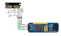
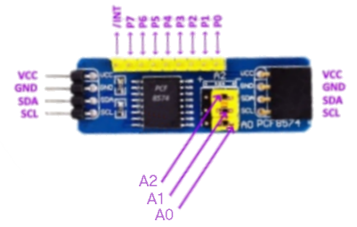
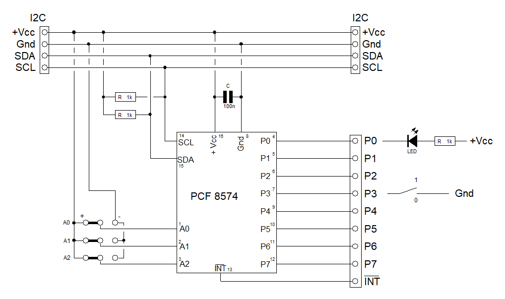
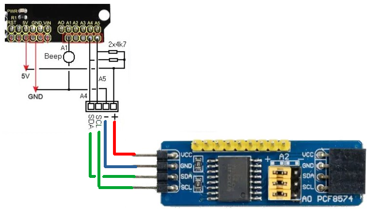
Introduction to the PCF8574 The PCF8574 is an I²C bus-controlled input/output expander. It provides 8 additional I/O lines and is an ideal solution when you want to control multiple devices with only two control wires (SDA and SCL). The PCF8574 is available in DIP format (to be soldered onto a breadboard), but the PCB module version, already equipped with resistors and I2C connectors, is the ideal complement for an Arduino board.The three jumpers A0, A1, and A2 are used to configure the component's I2C address. When all three are in the “+” position (logic level 1), the 7-bit address becomes 0x27, which corresponds to 0x4E in GCBasic. The diagram is as follows : The PCF8574 pins can be used as outputs or inputs. The internal circuit architecture is very specific (each pin has an open-drain transistor associated with an internal pull-up current). In output mode, an LED connected to VCC via a resistor is generally connected. In this case, a low level (0) turns the LED on, while a high level (1) turns it off: the logic is therefore inverted. In input mode, a 1 is written to the pin, which places it in high impedance. If it is left free, it will be read as 1; if it is connected to ground, it will be read as 0. The INT pin signals any change in the state of the pins configured as inputs (0 if INT).
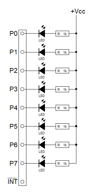
Using the PCF8574 – Output Operation After configuring the PCF8574 module at address 0x4E (test the module with the I2C scanner) and wiring the LEDs. You can easily test the module with the Test1_pcf.gcb program. This program simply uses the HI2C commands required for the PCF8574 to function. The comments make it easy to understand the program.
;Definition des variables Dim AdrPCF8574 as Byte AdrPCF8574 = 0x4E Dim Donnee, Allumage as Byte
Do Donnee = 0b00000101 Allumage = NOT Donnee HI2CStart HI2CSend ( AdrPCF8574 ) HI2CSend ( Allumage ) HI2cstop Wait 200 ms
Using the pcf8574 – Output operation - using the pcf8574.h library Using the pcf8574.h library further simplifies the program. Try the Test2_pcf.gcb program. There is no longer any need to use HI2C commands; everything is handled by the library. The comments make it easy to understand the program.
;Déclaration bibliotheque #include <pcf8574.h>
;commande specifique de la bibliotheque pcf8574.h PCF8574_sendbyte(PCF8574_DEVICE_1, Allumage )
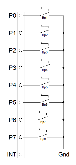
Using the PCF8574 – Input operation Wire the push buttons. You can easily test the module to read the BP values using the Test3_pcf.gcb program. The comments make it easy to understand the program. The binary display uses a subroutine. do PCF8574_readbyte(PCF8574_DEVICE_1, PortPCF ) AffichageBinaire Loop
Sub AffichageBinaire For Compteur = 7 To 0 step -1 Position = Compteur + 4 Binaire = PortPCF AND 0b00000001 Locate 0, Position If Binaire = 1 Then Print "1" Else Print "0" End If PortPCF = FnLSR(PortPCF, 1) NextEnd
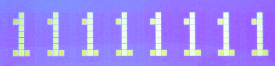
Bp1 to Bp8 open
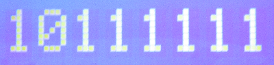
BP1 to BP6 open BP7 closed BP8 open
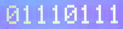
BP1 to BP3 open BP5 to BP7 open BP4 and BP8 closed
Using an LCD screen with an I2C controller An I2C LCD screen is actually a standard LCD display (often of the HD44780, 16x2 or 20x4 type) to which an I2C interface module, usually based on a PCF8574, has been added. Very inexpensive to purchase (around €6 for the whole thing on eBay), it is a great replacement for the classic LCD display, as it significantly reduces the number of connections required between the microcontroller and the screen: only two wires (SDA and SCL) are needed.
After defining the TWI bus, implementing an I2C display simply involves inserting the line :
#define LCD_IO 10
Try the Test4_LCD_I2C.gcb program. The comments make it easy to understand the program.
Want to build a project?
Bring your design to life with the Elektor PCB Service, powered by Eurocircuits. Upload the project files and order professionally manufactured PCBs or assembled boards through a proven European production platform.
Supporting KiCad, Eagle, Gerber, and ODB++ formats, the service is suitable for everything from prototypes and validation builds to series production and volume manufacturing.
Das Elektor Magazine gehört seit 65 Jahren zu den führenden Informationsquellen für Elektronikingenieure, Entwickler, Start-ups und Unternehmen. Unser Magazin wird von einer aktiven Community aus Elektronikingenieuren – von Studenten bis zu Profis – getragen, die mit Leidenschaft innovative Ideen entwickeln und teilen.
Für diese veröffentlichen wir jedes Jahr Hunderte von Beiträgen in Formaten wie Artikeln, Videos, Webinaren und weiteren Lernformaten. Unsere Mission ist es, Wissen auf jede mögliche Weise zu teilen und die Leser mit den neuesten Entwicklungen im Bereich der Elektrotechnik zu inspirieren.
Vielen Dank für Ihre Bewertung!
Kommentar hinzufügen
Vielen Dank für Ihre Bewertung!
Möchten Sie einen Kommentar mit Ihrer Bewertung hinterlassen? Bitte melden Sie sich unten an. Nicht gewünscht? Dann schließen Sie einfach dieses Fenster.

Diskussion (0 Kommentare)