
PC Watchdog [140344]
By Willem den Hollander(original text) Most microprocessors have implemented a so-called Watchdog function. A counter continuously counts down either a clock generated by a separate oscillator or the main processor clock. When the counter reaches zero a reset is generated.
By Willem den Hollander
(original text)
Most microprocessors have implemented a so-called Watchdog function. A counter continuously counts down either a clock generated by a separate oscillator or the main processor clock. When the counter reaches zero a reset is generated. By regularly reloading the counter before the counter reaches zero by including a particular instruction in the software, the watchdog is prevented from resetting the processor. This provides a tool to sense malfunctioning of the processor and to recover from such situation. A PC does not include this function. PCs are quite reliable today, but occasionally they might hang and stop functioning. Only a reset will bring them back to life. Many PCs including servers operate unattended and/or at a remote location. Here it would be very useful to have this function available.
The realization of a watchdog function for a PC is quite straightforward. At regular intervals a program on the PC generates a signal on an interface. A circuit receives this signal. When this signal is absent for too long a time, the circuit resets the PC.
The schematic of the circuit is shown in Figure 1. A PIC microprocessor with USB function receives at regular intervals a signal from the PC via the USB. The supply voltage for the processor is obtained from the USB. During proper operation of the PC the LED blinks green. If the PIC generates a reset, the LED is continuously red. During startup the LED is continuously green. The circuit is recognized by the PC as a HID device.
The PC program is started after Windows startup by placing it in the startup section of the list of program files. When the program is running with the external circuit present a little dog icon is visible on the taskbar as in figure 2a, otherwise the icon is shown as in figure 2d.
Right clicking on the dog icon shows different options for the software program – figure 2b. Selecting Standby puts the external hardware in standby (figure 2c) so that it will not produce a reset in the absence of input signals. Clicking on Activate will bring it back to normal operation. The function Open, which also can be activated by double clicking the dog icon, will bring up the window as in figure 3.
Here the different delay times can be adjusted. They will actually be stored in the PIC processor of the external hardware. The Delay after power on, the start up condition, defines how many seconds it will take in the absence of an input signal before a reset is generated. The range is between 10 and 255 seconds. If a zero is input, the circuit will never produce a reset until the first input signal puts the circuit in normal operation. If after the last input signal no input signal is received within the Receiver interval, the circuit will generate a reset. The 3 PC will send a signal via the USB to the watchdog circuit at a rate define in the Transmitter interval. The Update button activates the new values and causes them to be stored in the processor memory. The Standby button has the same function as described above and the Close button causes the window to close. The program can be exited by clicking the cross at top right.
Since the mini-USB connector seems to be only available as an SMD component, the resistors and capacitors are SMD components as well. The reset output has to be connected in parallel with the reset switch of the PC. Probably the easiest way is to tap the wires going from the reset switch to the motherboard.
From the lab
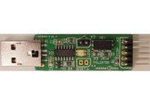
Originally the circuit was designed to be connected through a mini-USB cable. Since the circuit has to be connected to the reset of the PC we designed a PCB that can be put inside a free USB port on the back of the computer. That way a wire to the reset switch (or the corresponding header on the motherboard) can be short and it saves another cable hanging on the back of a your PC (or wherever). The PCB is designed to fit inside a small USB enclosure, like a big memory stick (see BOM).
In the original design only a MOSFET T1 was used. In most cases USB ground will be the same as ground of the reset switch and only one wire has to be connected. Generally the reset signal is pulled to ground level to reset the PC. This concept will be true for most PC’s. For those who are in doubt we added the option to make use of a small reed relay. Its contacts can be connected in parallel to the reset switch in a galvanic isolated way. Connecting solder jumper JP1 (very small, next to D1) will enable the relay. If enabled, it’s best for K4 (output of T1) not to be used anymore. The relay switch is available on K3. When using the relay it doesn’t matter how to connect the two wires, the polarity of the reset switch is irrelevant. Of course it’s also possible to use the relay for other purposes. But be careful, the relay contact can only handle 170 V and 0.5 A (both DC or peak AC). Furthermore it’s not meant for mains application! The relay is not the easiest part to solder. It can be done with hot air or if the entire PCB is soldered in one go in a reflow oven. For now it’s decided that only the bare PCB is available. Except for the relay, the rest of the parts are fairly easy to solder. If the relay is not used D1, R3 and K3 can be left out. If a pin header is to be used for K3 or K4, cut it so it won’t be higher than 5.5 mm above the top side of the PCB. Otherwise the PCB won’t fit inside the small enclosure. The solder pads of the connecters K3 and K4 are large enough to solder wires directly to the PCB and save on the header (you only need one 2-way pin header! K3 or K4). Where exactly the wire(s) should come out of the enclosure is one’s own choice, but probably somewhere between the two parts of the enclosure.
The ICSP header K2 can be used to program the microcontroller. A PICkit 2 can be used (an update is probably necessary if the microcontroller is not recognized). Horizontal header K2 is positioned in such way the total length of the PCB and header fit exactly in the small enclosure (see photo). The header is one from our EPP list and about 1.6 mm longer than other similar versions.
In our first test run the watchdog kept resetting the PC a few seconds after the windows logo appeared (endless loop). We tested the circuit on an older/slow PC with Windows XP installed. Files can get damaged if the PC is reset in a hard way (scan disk will run at reboot), so it’s not something I was willing to do on my regular PC. Luckily it always proved to be a non-essential file. After getting advise from Willem we changed the default settings to 0, 25 and 10. For slower systems the difference between the settings for ‘Receiver interval’ and ‘Transmitter’ interval should be bigger. Even on a modern PC some programs can prevent the watchdog from sending a signal on time.
How to test the circuit? Well simply have your computer crash with some utility. We first tried creating a batch file to open an infinite number of command windows in an endless loop. That didn’t work. So we used a utility we found on the internet: http://nirsoft.net/utils/start_blue_screen.html
It Initiates a Blue Screen of Death (BSOD). Works like a charm. 5 command-line parameters have to be specified when executing the program StartBlueScreen.exe to initiate a Blue Screen of Death. Create a batch file with one line: ‘StartBlueScreen.exe 0x12 0 0 0 0’.It worked. We got a blue screen and a few second later (depends on where in the interval the BSOD is initiated) the computer was reset and after booting a message stating the computer was reset by the watchdog appears.
Software for the PC was developed using Delphi XE4. Both source for the PC software en firmware for the processor are included in 140344-11.zip. To install watchdog on your PC just run ‘Watchdog setup.exe’.
Bill of materials
Resistor
R1 = 10 kΩ, 5%, 0W1, SMD 0805
R2 = 1 kΩ, 5%, 0W1, SMD 0805
R3 = 47 Ω, 5%, 0W1, SMD 0805
R4 = 22 Ω, 5 %, 0W5, SMD 1206
Capacitor
C1 = 100 nF, 50 V, X7R, SMD 0805
C2 = 470 nF, 50 V, X7R, 0805
Semiconductor
LED1 = SML-LX1210IGC-TR, dual led red/green, 160°, SMD 2.7x2 mm
D1 = TS4148 RY, SMD 0805
T1 = 2N7002, SMD SOT-23
IC1 = PIC16F1455, SMD SOIC-14
Other
K1 = USB Plug, 2.0 Type A, right angle, SMD (2410 07, Lumberg)
K2 = 5way pin header, SIL, horizontal (4-103323-1, TE-Connectivity)
K3,K4 = 2way pin header, SIL, vertical (only one or none needed, see text)
RE1 = CRR03-1A (Standex Meder), dry reed relay, SPST-NO, 3 V/70 Ω, 170V/0A5
Misc.
Enclosure Strapubox USB 1, transparent, 56x20x12 mm (Conrad 531276)
PCB 140344-1 v1.1
Want to build a project?
Bring your design to life with the Elektor PCB Service, powered by Eurocircuits. Upload the project files and order professionally manufactured PCBs or assembled boards through a proven European production platform.
Supporting KiCad, Eagle, Gerber, and ODB++ formats, the service is suitable for everything from prototypes and validation builds to series production and volume manufacturing.
Made in Europe. Fast. Reliable. Professional.
Diskussion (1 Kommentar)