
Outdoor Solar/Wind Wireless Wifi/3G Webcam & Wifi hotspot in option:
Many of us want to receive regularly a picture of a place, which can be a beach for activity, a second house, a place in mountain for hiking or biking. Also, it can monitor a house under construction or other daily monitoring needed.
Many of us want to receive regularly a picture of a place, which can be a beach for activity, a second house, a place in mountain for hiking or biking. Also, it can monitor a house under construction or other daily monitoring needed.
But if there is no power, it's become complex. Solar is a good option but the power need for a webcam or another equipment will request large solar panel.
At beginning, I tried and it was working with Wifi IP cam. From the LiPo battery, need a step up for the 5V 500mA of the camera. It was working but need larger solar panel and the picture quality of these Wifi IP camera was poor, around VGA definition. In a second version, I tried to use a smartphone to do this task.
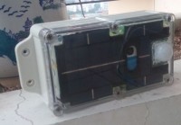
What I built already is a compact webcam, into waterproof enclosure, 140*80*60mm, with a solar panel embedded which can send picture every 3h or more, with choice of day and night and with an option for PIR working as an alarm.
Features:
- Standalone webcam solution with embedded or external solar panel by wifi, 2G/3G
- Can send picture on FTP or/and email on regular basis, 3 min to hours
- Can have SMs features to take picture at demand
- Low consumption to optimize the panel size and compactness
- Enclosure waterproof IP67 size 16*8*6 cm
- Adaptive upload frequency depending of the charge level of the battery
- Day and night function for uploading the picture
- Measure the current of charging, instant and cumulative
- Possible alarm with PIR option
- On testing (see at the end) with live cam
Implementation:
The solution is to use a simple modified smartphone (I'm using Alcatel One Touch brand because it is reliable) and power it only when need send a picture. An embedded available APK will connect to the network 2G/3G or Wifi and send picture to FTP server or/and email.
A low power control board, with Microchip controler manages the whole system. In case no more power, hardware will protect the battery and restart safely. Already 15 samples, built, 3 different versions and can be look on the demo page:
http://demo.solarcamlab.com
On this demo page, some just outlooking pictures, or construction building pictures.
I use it also for a weather page, with a solarcam on the balcony: http://weather.solarcamlab.com Laurent
The image containts the battery level in %, the temperature. If the battery level decrease, the upload frequency will decrease.
The control board with the PIC 18F2420 is managing the switch on of the handset, regarding the battery voltage, the outdoor light (day/night function), the PIR input for alarm function. Also, it is measuring the input current which is charging the battery. It is usefull for checking if the place has enough current to recharge the battery.
An option possible and implemented already (see webcam in Huizhou) is to have full time on the handset and send SMs when picture need. In this case, it can be only on demand or/and with regular upload.
A version with a larger solar panel external is under test. The target is to upload a picture every 2 minutes.
On the 4th PCB version, there is possibility to have 2 solar panel, IR remote control (SW not yet developped), display function on the internal display regarding the charging status or not.
Principle of the control board:
Organized around a Pic 18F2420, with internal slow clock 1Mhz for consumption, there is first an hardware power management with an AOP Maxim Max931. When the battery is more than 3.6, the Pic start to work and the power will be shutdown if less than 3.2V. I'm using extended temp of this Maxim IC.
When the Pic start, it's display the current option status. All the timer control is done here, with 3 button of MMI. The user can select when the camera need to switch on, period and how long stay on, 1min to 20. Depend of the network, data rate and so.
It can be select also day and night working. Another option is to keep the camera all time ON (normal behavior is OFF all time except to send picture) and can work with SMS command in 2G/3G option.
In normal working time, the Pic manages the sending picture by switch on the mobile. The trick here is not trivial. How to switch off automaticely the mobile. Several option, all hardware (never found a SW solution).
To switch on, I choose some smartphones from AlcatelOneTouch which has an MTK baseband. Some of these MTK chipset support autoswitch off and can work normaly if the ON button is full time press. So, the handset is modified by making a soldering join on the FPC of the switch on button. working fine. All the time the power is put on the handset (battery), the handset start. At the end, the APK start automaticely and send the picture. After xx minutes, the Pic switch off the power and the handset switch off.
On Wifi, all was working well but in 3G or worse in 2G, the high current needed to send the data setup the low battery alarm. The final solution was to put a 4700uF close to the handset to absorb all these peak current.
The handset is modified also on the battery connector. There is a NTC to manage before the battery safety and now used for display the camera temperature. Last trick, a 10k resistor is needed to reconnize the battery as original one by the chipset. without, some phone didn t work.
For the charging of the Lithium battery, I tried several option, first based on Maxim chip, Max1555 and so. All of them has trouble when power with the solar panel. Finaly, I founbd a simple one, TSOP 5 pin, from Eutech EUP8054. It can accept up to 600mA charging current and the max current can be adjust with external resistor. Here, it is put at 600mA max. The datasheet in the document hereafter.
About the solar panel, all options are possible. To optimize the surface of the waterproof enclosure, I ask a solar company to develop a full surface solar panel with just a hole for the camera. But there is also some option for outside solar panel, bigger.
Software:
Writen in C, it is a loop with sleep mode at the end. Wake up every 256 ms. all of this to optimize the consumption. Using the 1Mhz clock internal.
I cannot say it is optimize SW and it was quite simple at beginning and now with lot of new features. It is also compatible with LCD in // interface and now I2C intefface.
As it is for an SOP 18F2420, there is a boot for download by serial link. I'm using a very good bootloader from Claudiu:
http://www.etc.ugal.ro/cchiculita/software/picbootloader.htm
The link is done in 5v serial link with an external USB/serie convertor 5V. To interface with the 3.3V, some precaution has to take.
There is in the Sw a display of the instant current charging and also, total from beginning. It's help to check the total charging current in one position. All this SW part is coming from another project which monitor the consumption of an equipment. anoter project to present here later...
APK:
I tried many apk. The condition was to be able to autostart after power on, send email and upload on FTP server. At the end, I choose mobilewebcam, an excellent apk which can do many things. It has some options me didn t work well, so spent lot of time to find the right configuration and also, the most optimum one for save energy. The fallback is this apk parameters cannot be change at distance after embedded (the option didn t work), the support is so-so but the current status is already very good.
I'm looking for a backup solution, any idea is welcome here. Or to develop myself such apk but still long way to go...
New PCBA V4:
Similar features but with most of the component in discrete (better for the eyes during soldering), routing optimization for control the handset (close to the battery connector), 2 solar panels option and some new features to be develop on Sw with a measurement of the solar panel voltage. I'd like also to develop different display mode during charging or without.
Evolution in December 2013:
One new feature with hardware change and SW develop:
- Now, the handset can be start by the power on button (put to ground). Before it was only with the battery power start. This can help to use some other mobile and some other plateform which didn t support the start with on button short circuit
Another hardware change for low voltage start. Optimize the start with low battery and avoid a possible leakage current in the handset.
A new utilisation on testing:
- Live camera with a bigger solar panel and a new APK in the smartphone. With a router wifi configure to receive connexion and a correct port forward, it works...
January 2014:
- Post picture of the last modified PCB V4 with button power on simulation. Found some power input from handset to the Microchip CPU so need to add one 1N4148 to isolate.
- Made lot of consumption tests (using another development I plan to present here later) on wifi and 2G and 3G network. Plan to do an excel sheet to estimate which size of solar panel request regarding the frequency of the update needed. But most of time, the embedded one looks enough with 150mA.
May 2014:
- Several tests done. The optimize frequency for the 180mA solar panel is around 30 min. It can keep the battery at good level.
- Develop and successfully test the alarm version with the PIR. Works fine.
- For higher frequency, a version with external solar panel and weather proof plug
=> On the website, more pictures about some already installed. Mainly for construction check, sport activity, second residence check.
http://www.solarcamlab.com/solarcam_detail_e.htm
- Next step is to update the PCB with a version where the setup will be easier
July 2014:
- New PCB V5 is there. With a simulation of the ON button of the handset, no need now to manipulate the handset (picture joined)
- Improvement of the SW in low battery
- Working well with an external solar panel and with a voltage limiter on the PCBV5 and a BD135 to absob the over power
- Still trying the video mode. Can work well with the external solar panel.
- Some optimized panel on mock up to get more current
September 2014:
One of the major inconvenient of the current solution is to be impossible to change the timer parameter (inside the control board) after setup and close the box.
I'm working to introduce this capability with SMS send to the mobile (in GSM mode). The SMS will be analyze and if it is a valid command, send to the USB link.
I plan to introduce an FT311D (thanks to recent elektor idea) to get the data and send to the UART of the PIC.
Finally, change the parameters.
I need develop special apk (I'm learing...) for this, then hardware with FT311D (I found small board ready to use here). Later, a new PCB with this feature plan.
February 2015:
- No important change in the recent topic except some Sw improvement.
- One major evolution on going is to add a wind generator for the place (like North Europe) where some times of the year, the sun is not enough. It was an evolution proposed by a reader of the website
- Another evolution for the very cold temperature (request also my an American reader). How can I add an heater inside the camera to woarn in case of temperature lower than -20 degres Celsius. Some tests on going.
- Last evolution: Add function of hotspot. With a sim card, can share the connection with another webcam through Wifi or to some computer. The camera will be in always ON mode, with hotspot and can share the connexion.
January 12th, 2016:
- For the alarm feature, the current function didn t work for instant upload. The PIR was detecting movement, then will start the smartphone and take the picture. It could be 1min to 1min30 sec between the detection and the picture send.
Finally, I found a solution by keeping the smartphone always ON (the function already exist) and the picture can be send by charger insertion detection. So, I have to simulate a charger insertion when the PIR detect a movement. This is done with an DC/DC converter, 3.8V (Vbat) to 5V. The mobile will not detect the charger is the voltage is lower than 4.5v. New PCb to be done with this new feature.
----------------------------------------------------------------------------------------------------
Laurent
Build This Project
Bring this design to life with the Elektor PCB Service, powered by Eurocircuits. Upload the project files and order professionally manufactured PCBs or assembled boards through a proven European production platform.
Supporting KiCad, Eagle, Gerber, and ODB++ formats, the service is suitable for everything from prototypes and validation builds to series production and volume manufacturing.
Made in Europe. Fast. Reliable. Professional.
Updates des Autors