
On/Off Button for Arduino; switching off software controlled
Switching Arduino on and off with just the press of a single button. Switching it off can be controlled by the running sketch.
Scroll down for English Version.
Im Gegensatz zum Raspberry Pi verfügt der Arduino nicht über eine Anweisung zum kontrollierten Herunterfahren (shutdown). In der Regel wird dies auch nicht benötigt, man kann das Board einfach stromlos machen, ohne dass irgend etwas Schaden nimmt. Anders sieht es aus, wenn auf dem Arduino ein Sketch läuft, der Schreibzugriffe auf eine SD-Speicherkarte vornimmt. Dann kann ein unkontrolliertes Ausschalten die Datei auf der Speicherkarte unwiederbringlich beschädigen und im schlimmsten Fall sogar die SD-Karte unbrauchbar machen. Am besten wäre es, man würde den Sketch entscheiden lassen, wann der Arduino ausgeschaltet werden kann, doch geht das?
Es geht, mit dieser Schaltung! Wie im Schaltbild zu sehen ist, besteht sie nur aus wenigen Bauteilen, zwei MOSFETs (einem P- und einem N-Kanal MOSFET), drei Widerständen und einer Diode. Bei letzterer muss man sich allerdings im Klaren sein, dass diese Lösung nicht ohne einen Eingriff in den Arduino gemacht werden kann. Allerdings hält sich der Aufwand in Grenzen und ist auch rückstandsfrei wieder umkehrbar.
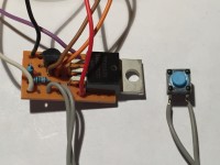
Doch der Reihe nach! Sinn der Schaltung ist es, den Arduino über den Druck auf einen Taster einzuschalten und einen erneuten Druck auf denselben Taster wieder auszuschalten. Das geschieht mit Hilfe dieser Schaltung softwaregesteuert, man braucht dazu zwei Pins des Arduinos. Die Stromversorgung des Arduino wird hinter dem Hohlstecker unterbrochen indem die Verpolungsschutzdiode ausgelötet wird. Da man für die Schaltung auch eine Diode benötigt, wird sie gleich recycelt indem sie mit der Kathode aufrecht stehend auf das frei gewordene Pad nahe der Connectorleiste auf dem Arduino wieder angelötet wird (siehe Bilder). Dabei muss darauf geachtet werden, dass auf dem Pad noch genügend Platz bleibt, um eine dünne Litze mit anzulöten. Nun kann man den Hohlstecker auf dem Arduino benutzen, um das Board mit einer +12V Spannung aus einem kleinen Netzteil zu versorgen. Diese Spannung wird der zusätzlichen Schaltung, die leicht auf einem kleinen Lochrasterabschnitt aufgebaut werden kann, zugeführt, die diese Spannung dann wieder an den Arduino zurück gibt; geschaltet selbstverständlich.
Wie funktioniert nun die Schaltung? Durch das Drücken des Tasters an den Eingängen 2 und 3 wird die Eingangsspannung unmittelbar an den Arduino weitergegeben; der Arduino startet. In dem auf dem Arduino laufenden Sketch muss man nun zuerst einmal dafür sorgen, dass ein Pin (hier: Pin 8 über PWR_CTRL Anschluss 7) HIGH geschaltet wird. PWR_CTRL ist mit dem Gate von Q2 verbunden und schaltet den MOSFET durch. Dadurch wird das Gate von Q1 auf GND gelegt, wodurch dieser ebenfalls durchschaltet. Der Taster kann losgelassen werden, da Q1 dafür sorgt, dass die Spannung dauerhaft über Leitung 6 zum Arduino gelangt. Leitung 6 muss also auf der Arduino Seite mit dem Pad verbunden werden, auf dem die zuvor aus- und wieder eingelötete Diode aufrecht steht. Die Leitung 5 (SENSE) ist auf der Arduino Seite mit Pin 2 verbunden und schaltet ferngesteuert über den Taster den Arduino wieder ab, wenn das durch einen Tastendruck eingeleitet wird. Dieser zweite Tastendruck bei eingeschaltetem Arduino zieht den SENSE Pin 2 auf HIGH Niveau, R2 dient der Strombegrenzung, während R3 als Pulldown Widerstand dafür sorgt, dass SENSE nicht floatet, wenn der Taster nicht gedrückt ist. Im Sketch muss dann nur noch zu einem strategisch günstigen Zeitpunkt (wenn der Schreibvorgang auf die SD Karte erfolgreich durchgeführt wurde) dafür gesorgt werden, dass PWR_CTRL Pin8 LOW wird; Q2 sperrt, über R1 liegt nun +12V Potenzial am Gate von Q1 an und dieser schaltet die Energieversorgung für den Arduino ab. Violá, das war’s.
Zu erwähnen ist vielleicht noch, dass abhängig von der Zeit, die der Bootloader braucht, der Arduino nicht sofort den Pin 8 HIGH schalten kann, zum Einschalten ist also ein etwas längerer Tastendruck erforderlich als zum Ausschalten. Am besten ist eine optische Anzeige wie zum Beispiel die LED an Pin 13 des Arduino oder ein LCD, auf dem durch die ausgegebene Meldung signalisiert wird, wann man den Taster loslassen kann. Im beigefügten gut dokumentierten Beispielsketch ist das mit einem LCD realisiert. Hier sieht man auch, an welcher Stelle die Ausschaltroutine eingebaut werden muss, damit das für die SD Karte nicht gefährlich wird.
Nebenbei bemerkt, wird durch die vorliegende Schaltung auch noch die Lebensdauer der SD Karte erhöht, da man nun nicht mehr permanent auf die Karte schreiben muss, um das letzte gültige Ergebnis zu sichern, sondern nur noch unmittelbar vor dem Ausschalten. Selbstverständlich kann man die Schaltung auch im Zusammenhang mit Schreibzugriffen auf das in der MCU des Arduino integrierten EEPROMs verwenden oder auch ganz ohne dies, nämlich einfach nur, um das Board ganz komfortabel ein- und ausschalten zu können.
English Version (complains about mistakes to Google Translate)
Unlike the Raspberry Pi, the Arduino does not have a shutdown command. In general, this is not needed, you can simply de-energize the board without any damage. The situation is different when a sketch is running on the Arduino, which writes to an SD memory card. Then an uncontrolled turn off can damage the file on the memory card irretrievably and in the worst case can even leave the SD card unusable. It would be best to let the sketch decide when the Arduino can be switched off, but is that possible?
It works, with this circuit! As shown in the diagram, it consists of only a few components, two MOSFETs (one P- and one N-channel MOSFET), three resistors and one diode. In the latter case, however, one must be aware that this solution can not be made without an modification of the Arduino. However, the effort is limited and can be reversed without leaving any residue.
But in turn! The purpose of the circuit is to turn on the Arduino by pressing a button and turn off by a new press of the same button. This is done with the help of this circuit software controlled, you need two pins of the Arduino. The power supply of the Arduino is interrupted behind the barrel connector by de-soldering the reverse polarity protection diode. Since you also need a diode for the circuit, it is recycled immediately by soldering it with the cathode upright on the vacated pad near the connector bar on the Arduino (see pictures). It must be ensured that there is still enough space left on the pad to solder a thin wire. Now you can use the barrel connector on the Arduino to supply the board with a +12V voltage from a small power supply. This voltage is supplied to the additional circuit, which can be easily built up on a small breadboard section, which then returns this voltage to the Arduino; switched of course.
How does the circuit work? By pressing the button on the inputs 2 and 3, the input voltage is passed directly to the Arduino; the Arduino starts. In the Sketch running on the Arduino you have to make sure that a pin (here: pin 8 via PWR_CTRL line 7) is switched HIGH. PWR_CTRL is connected to the gate of Q2 and turns on the MOSFET. This puts the gate of Q1 to GND, which also turns it on. The button can be released, as Q1 ensures that the voltage via line 6 permanently reaches the Arduino. Therefore, line 6 must be connected on the Arduino side with the pad on which the previously soldered and re-soldered diode is upright mounted. Line 5 (SENSE) is connected to Pin 2 on the Arduino side and remotely using the button switches off the Arduino when is initiated by pressing the button. This second button press with switched-on Arduino pulls the SENSE pin 2 to HIGH level, R2 is used to limit the current, while R3 as a pulldown resistor ensures that SENSE does not float when the button is not pressed. In the sketch, it is only necessary to ensure that PWR_CTRL pin 8 becomes LOW at a strategic moment (if the writing process to the SD card has been carried out successfully). Q2 turns off, via R1 +12V potential is now connected to the gate of Q1 and it turns off the power supply for the Arduino. Violá, that's it.
It may also be mentioned that depending on the time the bootloader needs, the Arduino can not immediately switch HIGH pin 8, so a longer button press is required to turn it on than to turn it off. The best is an optical indicator such as the LED on pin 13 of the Arduino or an LCD, which signales by a message, when you can release the button. In the attached well-documented demo sketch it is realized with an LCD. In this sketch you can also see where the shutdown routine must be implemented so it’s not dangerous for the SD card.
Incidentally, the present circuit also increases the life of the SD card, since it is no longer necessary to permanently write to the card in order to save the last valid result, but only immediately before switching it off. Of course you can use the circuit also in connection with write access to the Arduino’s MCU integrated EEPROMs or even without this, namely, just to switch the board quite comfortable on and off.
Im Gegensatz zum Raspberry Pi verfügt der Arduino nicht über eine Anweisung zum kontrollierten Herunterfahren (shutdown). In der Regel wird dies auch nicht benötigt, man kann das Board einfach stromlos machen, ohne dass irgend etwas Schaden nimmt. Anders sieht es aus, wenn auf dem Arduino ein Sketch läuft, der Schreibzugriffe auf eine SD-Speicherkarte vornimmt. Dann kann ein unkontrolliertes Ausschalten die Datei auf der Speicherkarte unwiederbringlich beschädigen und im schlimmsten Fall sogar die SD-Karte unbrauchbar machen. Am besten wäre es, man würde den Sketch entscheiden lassen, wann der Arduino ausgeschaltet werden kann, doch geht das?
Es geht, mit dieser Schaltung! Wie im Schaltbild zu sehen ist, besteht sie nur aus wenigen Bauteilen, zwei MOSFETs (einem P- und einem N-Kanal MOSFET), drei Widerständen und einer Diode. Bei letzterer muss man sich allerdings im Klaren sein, dass diese Lösung nicht ohne einen Eingriff in den Arduino gemacht werden kann. Allerdings hält sich der Aufwand in Grenzen und ist auch rückstandsfrei wieder umkehrbar.
Doch der Reihe nach! Sinn der Schaltung ist es, den Arduino über den Druck auf einen Taster einzuschalten und einen erneuten Druck auf denselben Taster wieder auszuschalten. Das geschieht mit Hilfe dieser Schaltung softwaregesteuert, man braucht dazu zwei Pins des Arduinos. Die Stromversorgung des Arduino wird hinter dem Hohlstecker unterbrochen indem die Verpolungsschutzdiode ausgelötet wird. Da man für die Schaltung auch eine Diode benötigt, wird sie gleich recycelt indem sie mit der Kathode aufrecht stehend auf das frei gewordene Pad nahe der Connectorleiste auf dem Arduino wieder angelötet wird (siehe Bilder). Dabei muss darauf geachtet werden, dass auf dem Pad noch genügend Platz bleibt, um eine dünne Litze mit anzulöten. Nun kann man den Hohlstecker auf dem Arduino benutzen, um das Board mit einer +12V Spannung aus einem kleinen Netzteil zu versorgen. Diese Spannung wird der zusätzlichen Schaltung, die leicht auf einem kleinen Lochrasterabschnitt aufgebaut werden kann, zugeführt, die diese Spannung dann wieder an den Arduino zurück gibt; geschaltet selbstverständlich.
Wie funktioniert nun die Schaltung? Durch das Drücken des Tasters an den Eingängen 2 und 3 wird die Eingangsspannung unmittelbar an den Arduino weitergegeben; der Arduino startet. In dem auf dem Arduino laufenden Sketch muss man nun zuerst einmal dafür sorgen, dass ein Pin (hier: Pin 8 über PWR_CTRL Anschluss 7) HIGH geschaltet wird. PWR_CTRL ist mit dem Gate von Q2 verbunden und schaltet den MOSFET durch. Dadurch wird das Gate von Q1 auf GND gelegt, wodurch dieser ebenfalls durchschaltet. Der Taster kann losgelassen werden, da Q1 dafür sorgt, dass die Spannung dauerhaft über Leitung 6 zum Arduino gelangt. Leitung 6 muss also auf der Arduino Seite mit dem Pad verbunden werden, auf dem die zuvor aus- und wieder eingelötete Diode aufrecht steht. Die Leitung 5 (SENSE) ist auf der Arduino Seite mit Pin 2 verbunden und schaltet ferngesteuert über den Taster den Arduino wieder ab, wenn das durch einen Tastendruck eingeleitet wird. Dieser zweite Tastendruck bei eingeschaltetem Arduino zieht den SENSE Pin 2 auf HIGH Niveau, R2 dient der Strombegrenzung, während R3 als Pulldown Widerstand dafür sorgt, dass SENSE nicht floatet, wenn der Taster nicht gedrückt ist. Im Sketch muss dann nur noch zu einem strategisch günstigen Zeitpunkt (wenn der Schreibvorgang auf die SD Karte erfolgreich durchgeführt wurde) dafür gesorgt werden, dass PWR_CTRL Pin8 LOW wird; Q2 sperrt, über R1 liegt nun +12V Potenzial am Gate von Q1 an und dieser schaltet die Energieversorgung für den Arduino ab. Violá, das war’s.
Zu erwähnen ist vielleicht noch, dass abhängig von der Zeit, die der Bootloader braucht, der Arduino nicht sofort den Pin 8 HIGH schalten kann, zum Einschalten ist also ein etwas längerer Tastendruck erforderlich als zum Ausschalten. Am besten ist eine optische Anzeige wie zum Beispiel die LED an Pin 13 des Arduino oder ein LCD, auf dem durch die ausgegebene Meldung signalisiert wird, wann man den Taster loslassen kann. Im beigefügten gut dokumentierten Beispielsketch ist das mit einem LCD realisiert. Hier sieht man auch, an welcher Stelle die Ausschaltroutine eingebaut werden muss, damit das für die SD Karte nicht gefährlich wird.
Nebenbei bemerkt, wird durch die vorliegende Schaltung auch noch die Lebensdauer der SD Karte erhöht, da man nun nicht mehr permanent auf die Karte schreiben muss, um das letzte gültige Ergebnis zu sichern, sondern nur noch unmittelbar vor dem Ausschalten. Selbstverständlich kann man die Schaltung auch im Zusammenhang mit Schreibzugriffen auf das in der MCU des Arduino integrierten EEPROMs verwenden oder auch ganz ohne dies, nämlich einfach nur, um das Board ganz komfortabel ein- und ausschalten zu können.
English Version (complains about mistakes to Google Translate)
Unlike the Raspberry Pi, the Arduino does not have a shutdown command. In general, this is not needed, you can simply de-energize the board without any damage. The situation is different when a sketch is running on the Arduino, which writes to an SD memory card. Then an uncontrolled turn off can damage the file on the memory card irretrievably and in the worst case can even leave the SD card unusable. It would be best to let the sketch decide when the Arduino can be switched off, but is that possible?
It works, with this circuit! As shown in the diagram, it consists of only a few components, two MOSFETs (one P- and one N-channel MOSFET), three resistors and one diode. In the latter case, however, one must be aware that this solution can not be made without an modification of the Arduino. However, the effort is limited and can be reversed without leaving any residue.
But in turn! The purpose of the circuit is to turn on the Arduino by pressing a button and turn off by a new press of the same button. This is done with the help of this circuit software controlled, you need two pins of the Arduino. The power supply of the Arduino is interrupted behind the barrel connector by de-soldering the reverse polarity protection diode. Since you also need a diode for the circuit, it is recycled immediately by soldering it with the cathode upright on the vacated pad near the connector bar on the Arduino (see pictures). It must be ensured that there is still enough space left on the pad to solder a thin wire. Now you can use the barrel connector on the Arduino to supply the board with a +12V voltage from a small power supply. This voltage is supplied to the additional circuit, which can be easily built up on a small breadboard section, which then returns this voltage to the Arduino; switched of course.
How does the circuit work? By pressing the button on the inputs 2 and 3, the input voltage is passed directly to the Arduino; the Arduino starts. In the Sketch running on the Arduino you have to make sure that a pin (here: pin 8 via PWR_CTRL line 7) is switched HIGH. PWR_CTRL is connected to the gate of Q2 and turns on the MOSFET. This puts the gate of Q1 to GND, which also turns it on. The button can be released, as Q1 ensures that the voltage via line 6 permanently reaches the Arduino. Therefore, line 6 must be connected on the Arduino side with the pad on which the previously soldered and re-soldered diode is upright mounted. Line 5 (SENSE) is connected to Pin 2 on the Arduino side and remotely using the button switches off the Arduino when is initiated by pressing the button. This second button press with switched-on Arduino pulls the SENSE pin 2 to HIGH level, R2 is used to limit the current, while R3 as a pulldown resistor ensures that SENSE does not float when the button is not pressed. In the sketch, it is only necessary to ensure that PWR_CTRL pin 8 becomes LOW at a strategic moment (if the writing process to the SD card has been carried out successfully). Q2 turns off, via R1 +12V potential is now connected to the gate of Q1 and it turns off the power supply for the Arduino. Violá, that's it.
It may also be mentioned that depending on the time the bootloader needs, the Arduino can not immediately switch HIGH pin 8, so a longer button press is required to turn it on than to turn it off. The best is an optical indicator such as the LED on pin 13 of the Arduino or an LCD, which signales by a message, when you can release the button. In the attached well-documented demo sketch it is realized with an LCD. In this sketch you can also see where the shutdown routine must be implemented so it’s not dangerous for the SD card.
Incidentally, the present circuit also increases the life of the SD card, since it is no longer necessary to permanently write to the card in order to save the last valid result, but only immediately before switching it off. Of course you can use the circuit also in connection with write access to the Arduino’s MCU integrated EEPROMs or even without this, namely, just to switch the board quite comfortable on and off.
Diskussion (2 Kommentare)