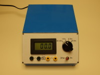
The Summer Circuits 2022 contained a circuit suggestion that I adapted to my ideas and my tinkering box
I have often wanted to be able to measure very small resistors or BLDC motors properly. When I looked in my tinkering box, I found most of the important components for this project.
However, I allowed myself a few deviations. For example, I still had a 6 volt power supply unit which I liked better than a battery or rechargeable battery power supply. These are usually empty exactly when you need the device. I also wanted to save myself the expense of a ready-made, expensive DC voltage converter for the potential-free supply of the digital voltmeter; I had already built something similar in the past. This somehow took me longer than I thought, but in the end my experiment with a DIY transformer made from a small shell core worked.
I also didn't want to buy the selector switch as I still had a similar part from a printer switch. However, it only had two positions and it was a mental exercise to extend it to 4 stages. Looking at the sensitive contacts of the switch made me doubt whether the selector switch could really withstand the measuring current of up to 1 ampere in the long term and might not cause a significant error or even "smoke out". So I switch the current with three relays, which also makes the wiring easier.
The power supply works with two secondary windings and two-way rectification, so I was able to obtain the 24V for the relays from the transformer. The backlight of the digital voltmeter, which needed more than the stabilised 6 volts, could also be activated as a "switch-on control".
It also took me a little time to recognise the traps that Elektor had probably included in the circuit diagram. The resistance values for 1mA current are quite wrong, and you also have to look at the data sheet for the LM317 to be able to make the correct wiring.
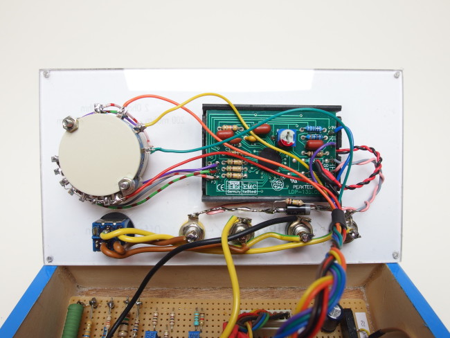
The back of the front panel. Thanks to the relays, the tangle of cables could be kept to a bearable level.
In Elektor, special test leads are recommended to eliminate the resistance of the cables. However, the problem of contact resistance remains with this suggestion. I have simply installed two more sockets and can work with four cables. This means that the voltage to be measured across the device under test is independent of the resistance of the cables carrying the measuring current and the contact resistance of the terminals. However, as this is not always necessary, I can connect the sockets with a switch and then also work with two normal cables.
I have broken new ground for the first time in the construction of the housing. I have little trouble building an enclosure from a few plywood boards. The problem is rather to create an attractive surface. So I came up with the idea of ironing a hot-glue-coated film from model aircraft construction onto the raw plywood surface. This quickly resulted in an attractive and sufficiently hard-wearing exterior for the device. I also always have difficulties with the front panels and their labelling. I drew the texts for the controls on the computer and printed them out. The paper is now simply clamped between two thin panes of plastic glass.
I think the result looks well. Literally, but above all technically. After adjusting the current sources with the trim pots or by connecting fixed resistors in parallel, I have a sufficiently accurate measuring device for small resistors.
As my English skills are still in need of improvement, I have translated this text with "deepl.com".
Build This Project
Bring this design to life with the Elektor PCB Service, powered by Eurocircuits. Upload the project files and order professionally manufactured PCBs or assembled boards through a proven European production platform.
Supporting KiCad, Eagle, Gerber, and ODB++ formats, the service is suitable for everything from prototypes and validation builds to series production and volume manufacturing.
Das Elektor Magazine gehört seit 65 Jahren zu den führenden Informationsquellen für Elektronikingenieure, Entwickler, Start-ups und Unternehmen. Unser Magazin wird von einer aktiven Community aus Elektronikingenieuren – von Studenten bis zu Profis – getragen, die mit Leidenschaft innovative Ideen entwickeln und teilen.
Für diese veröffentlichen wir jedes Jahr Hunderte von Beiträgen in Formaten wie Artikeln, Videos, Webinaren und weiteren Lernformaten. Unsere Mission ist es, Wissen auf jede mögliche Weise zu teilen und die Leser mit den neuesten Entwicklungen im Bereich der Elektrotechnik zu inspirieren.
Vielen Dank für Ihre Bewertung!
Kommentar hinzufügen
Vielen Dank für Ihre Bewertung!
Möchten Sie einen Kommentar mit Ihrer Bewertung hinterlassen? Bitte melden Sie sich unten an. Nicht gewünscht? Dann schließen Sie einfach dieses Fenster.

Diskussion (3 Kommentare)