
Microcontroller Board Stacking System
Introduction
Introduction
At this stage I am presenting a concept rather than a project ready to be built. In a nutshell, the concept is a rethink of the board stacking arrangement used in microcontroller systems such as Arduino and BeagleBone. The idea is to make the boards square with the stacking connectors symmetrically arranged on the four edges. IO boards can be plugged into the stack in any of four orientations which gives four different mappings onto microcontroller pins. In most cases this will allow four IO boards, even four identical boards, to be stacked without conflicting.
Reference Design
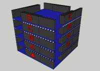
The reference design uses a 50mm square board (a little smaller than either Arduino or Beaglebone). Each edge has a 22 pin stacking connector of the same commonly available type used in the Arduino. Probably four of these contacts will be needed for power and these must be common on all four sides. The remaining 18 contacts connect to the IO pins of the microcontroller for a total of 72 IO pins divided between the four edges. The spaces to the left of each edge are intended to accommodate off-board connectors such as mini or micro USB, micro HDMI, or right-angle pin headers (up to four pins) for servo motors etc.
The four edges of the stack are referred to as "N", "E", "S" and "W" clockwise with the "N" edge marked with the red triangle on the microcontroller board (echoing the cardinal directions on a compass). The edges of the IO boards are labeled "A", "B", "C" and "D" clockwise. The four possible orientations of an IO board are referred to by the letter that corresponds to "N" on the stack. An IO board should be designed such that it consumes IO starting on its "A" edge. If it needs more than 18 IO pins, it should move next to the "C" edge, then "B", and finally "D". A board using one edge only may be stacked with four similar boards, if it uses two edges it may be stacked with one additional similar board or with two boards using one edge only. Even a board that requires three edges may always be stacked with one board that uses one edge only. As with the conventional stacking arrangement, boards may be fitted in the same orientation if they use different IO pins, so stacks of more than four boards will still be possible in some cases.
Microcontroller chips have a wide range of different pin availability, configuration options and specialist peripherals. The flexibility of this system depends on achieving the maximum amount of commonality between the pin assignments on each edge of the microcontroller board. The following standard is proposed for the connector with the extent of implementation depending on the facilities available on the specific microcontroller.
- For a small microcontroller it is permissible to provide sockets on the N and S edges only (fewer than two edges would not be mechanically stable).
- Priority should be given to fully populating the "N" edge, next the "W" edge, then "S" and finally "E".
- At least the first four digital I/O pins should be provided and if possible they should support hardware PWM and interrupt capability.
- Next, at least the first two analogue input capable pins should be populated.
- Then SPI, UART and I2C pins are populated with specified assignments for each pin function.
- Finally the rest of the connector should be infilled with remaining GPIO pins.
- If the microcontroller supports USB, this should not be routed into the stack, instead a micro or mini USB connector should be provided in one of the off-board connector spaces.
Implementation
My preference for an initial physical implementation of these ideas is to base it on one of the Cypress ARM-based PSOC chips. These strike me as well suited to the Elektor demographic. A highly flexible peripheral structure with programmable digital logic and configurable analogue components far beyond the norm make it well suited to ambitious mixed-signal projects with an electronic engineering rather than a computing flavor. There is an excellent, unlimited and free IDE (although Windows only), so it is quite hobbyist friendly.
Potential
However, the ideas are flexible enough to support most microcontroller systems with an interchangeable ecosystem of IO boards. It could even be the basis for yet another Arduino clone!
Diskussion (0 Kommentare)