
Mesh of LoRa radios - versatile yet easy! Now modified with Serial display
LoRa mesh can deploy the LoRa radios to get the best of networking for all good things like low-power, great ranges and impregnability. It's fun to play with the network. After setting up the nodes one can disconnect the android / IOS devices and the nodes will be working automatically.
Meshtastic – mesh of LoRa radios
[Meshtastic LoRa mesh is now modified with Meshtastic-mesh-network-with-Serial-out-terminal- see details in the attachment]
Node & Network :
[Meshtastic LoRa mesh is now modified with Meshtastic-mesh-network-with-Serial-out-terminal- see details in the attachment]
Node & Network :
Ever since LoRa [Acronym for Long Range ] radios hit the market lots of IoT devices are appearing in the market every now & then. Besides LoRa there is one more radio which is already occupying the market segment with variety of applications and that is Zigbee radios. Although zigbee radios are substantially costly still they are in use due to their exceptional easy meshing capability. Zigbee radios can be placed in mesh configurations where every Zigbee will be connected as a node with each other such that if one or many nodes fail the network will still be available!
While the Zigbee network is highly scalable the LoRa network is not lagging much behind. Besides LoRa has very long range, low power consumption, highly encrypted and immune to electromagnetic interferences.
Meshtastic network:
meshtastic.org has brought this open source software to create LoRa mesh network. LoRa works great on LOS [Line Of Sight]. Therefore, if one or two nodes can be placed at a strategically high place then all the nodes will be talking to each other easily. Already lots of works are available at Internet here I just tried to create a practical working network for readers where sensor data, GPS positio and triggering alarm can be worked out with ease which can be scaled next for bigger use.
BOM: Heltec ESP32 LoRa / ESP32 MCU with I2C OLED & SPI LoRa - 3set – either readymade or home made [see detail]
BME280 / MCP9808 - I2C sensors - 01.
uBLOX GPS Sensor – 01.
Since this is no Arduino programming where we can change the connections to our advantages, we need to have fixed connections in line with Heltec Lora-ESP32 right next to ESP32. Though this is not very difficult if you follow my instructions lest you can buy the “ESP32 Heltec LoRa” from market.
https://robu.in/product/esp32-lora-sx1278-0-96-inch-blue-oled-display-bt-wifi-module-for-arduino/ [INR:1882]
[The Heltec LoRa module]
The above module is also available at amazon.in for higher cost. However, if you dare to walk in my line to build your own handmade ESP32 Heltec Lora module in less than INR:1500 these are the raw materials which you need to procure first – An ESP32, an OLED [0.96”] and an SPI LoRa radio.
SX1278 868MHz LoRa Radio: https://robu.in/product/lora-module-rfm95w-868s2r/ [INR:665]
ESP32 Dev module: https://robu.in/product/esp32-38pin-development-board-wifibluetooth-ultra-low-power-consumption-dual-core/ [INR:463]
I2C OLED 0.96 Inch: https://robu.in/product/0-96-inch-yellow-yellow-blue-oled-lcd-led-display-module [INR:210]
Sensors: https://robu.in/product/gy-bme280-3-3-precision-altimeter-atmospheric-pressure-sensor-module/ [INR:579]
The I2C sensors you need to buy separately.
[ robu.in is an Indian store. Internationals can try amazon.com , aliexpress.com or alibaba.com USD $1 = INR 82.00 ]
Readymade devices: Heltec LoRa, T-Deck, Lilygo T-Echo etc are available in the market. While Heltec LoRa & T-Echo are mostly tested devices not much informations available for T-Deck.
The project construction:
To make a workable mesh network for testing we need to have 3 or more LoRa node built in line of the above schematic or purchased ready made ESP32 Heltec Lora board from market. Atleast one I2C sensor from the list to be procured [BME280, BME680, MCP9808, INA260, INA219, SHTC3, SHT31, PMSA0031 ]. Now to flush each ESP32 board with meshtastic software – connect the board to the USB terminal of your computer and then go to https://flasher.meshtastic.org/ This link works only in Chrome or Edge browser. However, for cli method of uploading does not have this restriction.
Schematic of ESP32 Heltec LoRa:
in the first screen select the firmware version you want to flush with [Heltec V1] and then in the next screen select the CP2102 USB to UART bridge... that is the interface hardware that sits in between the MCU and the Computer. Next follow the instructions that appear on the screen – like warning for erasing the entire device etc. Ensure the Internet connections is stable during this crucial 4 to 5 minutes duration. For the built in Heltec board you may need to keep the 'boot' button pressed for the entire 4 to 5 minutes of uploading phase.
Uploading software:
[by command-line-instruction method] This is also I'm providing as I find that the browser based firmware updation does not work reliably. Many a times it shows that it has completed the task very quickly but actually it does not do. It takes about 4 to 5 minutes time for installing / updating the firmware. That's why I'v provided the firmware and the cli method. Also to note that the software is going to change many times henceforth. Therefore, having a stable copy around may prove useful during later setup.
Mac Commands / Linux Commands
pip3 install --upgrade esptool [upgrade esptool first]
esptool.py chip_id [you will get a long output with chip id and chip mac id]
cd ~/Downloads/firmware/ [firmware-heltec-v1-2.2.12.092e6f2.bin]
./device-install.sh -f firmware-BOARD-VERSION.bin [for installing]
./device-update.sh -f firmware-BOARD-VERSION.bin [for updating]
Windows Commands
device-install.bat -f firmware-BOARD-VERSION.bin [for installing]
device-update.bat -f firmware-BOARD-VERSION.bin [for updating]
*** The present Meshtastic flasher site [flasher.meshtastic.org] does not provide flash facility for Heltec V1 or V2 board. It starts from Heltec V3 board and higher level boards like T-Beam , T-Echo, T-deck etc. The flash software firmware-heltec-v1-2.2.12.092e6f2.bin will flash the Heltec LoRa board or the Heltec LoRa homemade board as shown in the schematic.
Project testing:
To test & set the project we need to install meshtastic app in our android / iphone / IOS or tab. There are android & IOS version available in the respective software store [play store / app store] . For three nodes to work with I would request to fix one mobile / tab / Apple computer for each one node to play with. That way you will actually avoid many setup jolts which I learned in a bitter way. The app is absolutely free therefore no problem!
First power on the Heltec board. Next in your mobile /tab / apple pc switch on the bluetooth & pair with the Heltec board. The 6 digit pairing number will appear on the OLED screen. Once connected then open the meshtastic app and you will find the app is connected [look for the tick mark on top right] with the board with board's mac address. You can set a name for the board in the radio-configuration by pressing on the three dots (…) on right top of the app.
Attaching sensors:
Only I2C sensors [on addresses 0x76, 0x77, 0x78, 0x18, 0x40, 0x41, 0x5D, 0x5c, 0x70, 0x44, 0x12, 0x3c (fixed for OLED) ] are allowed. More sensors will be added in the coming days. In the Radio-configuration->Detection Sensor->Detection Sensor enabled.
You may provide a name to the sensor [BME or Temp_Ind]. In the same window you can also designate a GPIO pin to monitor for [hi or low] and the detection will be monitored periodically every 900 seconds [default value] for hi or low. Please note this GPIO pin status is totally independent of the sensor value.
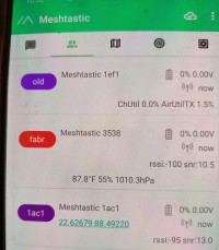
The home made Heltec is up now. I named it fabr [short for Fabricated one]. The other two are not up yet. That's why questions marks are appearing against their names. The tick mark on the top right cloud indicates that this node is connected.
Role:
In Radio Configuration->Device->Role [For transmitting Sensor value I made it ‘SENSOR’] The other options are 'CLIENT' or 'ROUTER_CLIENT' , 'REPEATER' etc.
SENSOR used for devices that gather and send sensor data. Optimised for low power consumption and periodic data transmission. Strategically these are used for remote sensor data on solar panel or battery power.
CLIENT used for end-user devices that primarily consume and display data. These devices can also send commands but do not relay messages within the network.
ROUTER_CLIENT acts to relay message across the network. Typically configured with higher power settings and kept stationary to maintain network stability and reach.
REPEATER acts as signal booster. Enhances the range of the mesh network by boosting the signal. Strategically placed to cover larger areas or to connect distant nodes that are out of direct communication range. Like routers, they typically do not sleep to ensure consistent signal boosting.
Remote Hardware:
This is where you can send signals from remote sensors. You have to define GPIO pin first. However only digital read & digital write is enabled here.
External Notifications:
Radio configuration->External Notification->enable. You also have to set the output GPIO pins which will receive the notification. You can set LED / Alarm Buzzer / Alarm Vibrator on three different GPIO pins along with time duration of the alarm. In my 'fab' unit I have set the alarm on GPIO-16 to light on a LED for 2000 milli seconds. The sensor values will appear on the Android / IOS screen & on the OLED screen.
Adding a new node: Just set the node up and it will be added in the network very easily.
GPS Location:
If the board has GPS locator, it will deliver it automatically otherwise if the android / IOS device has location information turned on, it will deliver the GPS location which will be visible against that node in the app-window. The app has the facility to attach a separate GPS sensor for which you have to manually set the GPIO pins for Tx & Rx. Radio configuration->Position [in the pic, location is coming from the phone location service]. However, after setting the GPS sensor, the location data [Lattitude & Longitude] would come from GPS sensor. As per the site only uBLOX, GLONASS GPS sensors are supported at this moment. My very old GPS Sensor – V.KEL TTL GPS sensor also worked when connected. The PPS is connected to an LED which can be avoided to preserve battery life.
Network:
Radio configuration->Network->enable WiFi-> enter SSID & PSK. Doing this will make your node inaccessible by bluetooth. Then you have to access it by wifi or ‘command line meshtastic’ which is explained below [not very friendly]. You have to know the IP address of the node first [go to the wifi DHCP list and find out it’s ip address & port usually nil ]
$> meshtastic --host <device-ip> --info
$> meshtastic --host <device-ip> --sendtext "Your message here"
For reversal of this just reinstall the firmware again. Though I tried many ways but it never worked. Therefore, reinstall is the only way!
Store & Forward: Radio configuration->Module configuration->Store & forward. Fortunately this works for ESP32 only. Here you can store a few records in the event of disconnection from node. However, Meshtastic does not recommend to use it normally.
Serial terminal: This I just love it. You have some sensors which you want to monitor but these sensors are not I2C type. Then attach them to an Arduino & send it over Serial port … into the serial terminal of Meshtastic node. The data will be read and transmit over the nodes. On the same line you can attach a serial monitor on these two GPIO pins such that you can monitor the serial data output directly. I have made one ‘ESP 32 Serial terminal viewer’ which can be tried at this elektor lab link - https://www.elektormagazine.com/labs/esp32-serial-terminal
Channel configuration: At some point you may need to make your network separate from other networks available in the air, running on the same frequency band! Meshtastic networks can be secured by setting a custom channel key (a shared secret 32 byte key) that is used to encrypt the messages. Only devices with the same channel key can join and communicate within the network. Radio Configuration -> Channel configuration; enter your secret-key and repeat it for all the a nodes. Instead of secret key, you can also set up an unique channel name to separate your network from other networks in the air. The secret-key should be a 32 byte encoded key. There is a small circular arrow on the right of the Channel key window. If you press it, it will provide you a random 32 byte encrypted channel key. Lest you can have a small python code for creating your own channel key -
Channel-key.py
import base64
key = "abcdefghijklmnopqrstuvwxyz123456"
encoded_key = base64.b64encode(key.encode()).decode()
print(encoded_key)
Command line meshtastic: While the app is OK for many, there is a command line meshtastic to work with the meshtastic hardwares. Connect the device on USB port.
$> pip install --upgrade pip [or pip3]
$> pip install meshtastic [or pip3]
$> meshtastic --version
$> meshtastic --help
$> meshtastic --port /dev/usbserial-xxxx --info [usbserial-xxx is the port number ]
$> meshtastic --setkey abcdefghijklmnopqrstuvwxyz123456 [to be encrypted channel key]
$> meshtastic --setch-name “S_Bera_SecureMesh” [Set the channel name]
Typical Use:
In a forest area using LoRa mesh one can monitor forest fire. In such case each node will monitor air temperature , velocity & humidity of it's zone. In an industrial area such mesh can be used very effectively for monitoring fire hazards. In a city turning all vehicles in LoRa node the vehicle speed & position can be monitored. In a township / housing complex, using V53LOX laser sensors all the water tank levels can be monitored. Same way in a township all the operating lifts [which are a LoRa node] will be monitored from a central monitoring centre. Chat with the nodes and or using MQTT reaching out to the other cities is also possible in Meshtastic LoRa networkings.
Aftermath:
The meshtastic software has shown how a LoRa mesh can deploy the LoRa radios to get the best of networking for all good things like low-power, great ranges and impregnability. It's fun to play with the network. After setting up the nodes one can disconnect the android / IOS devices and the nodes will be working automatically.
LED alarm fires up!
Prototype – ESP32, LoRa & OLED screen. BME 280 sensor is added.
S. Bera / Kolkata
Updates des Autors