
Making a Mini Monitor for Raspberry Pi
Raspberry Pi Monitor
INTRODUCTION:
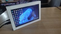
In this Project, I am going to show you how you can build a DIY mini Monitor for Raspberry Pi. This monitor can be used as a computer monitor because it has VGA and HDMI inputs. It can be easily connected to any CPU. This monitor also has a composite video input, so you can apply your video signal at this input and can use it as a mini LCD or LED T.V. . This monitor has neither speaker inside the case nor an audio input so if you want to use it as a mini T.V. ,you will have to use speaker separately along with monitor. This monitor has 10.1" Display. DIY mini monitor operates on 12V, 2Amp DC Power supply. You can supply power to it through a 12V, 2 Amp adapter. This monitor also has some buttons on its right side to select the inputs(AV1, AV2, HDMI, or VGA) and change the settings of the monitor. Although an infrared remote also comes along with display and driver board but I did not find it in my parcel. For changing the display settings and selecting the video input you can use buttons. Now let's get start!.
Supplies
Hardware Requirements:
- LCD pannel with Driver board(
- HDMI Cable
- 12V, 2Amp SMPS(Adapter)
- MDF Sheets (thickness = 3 mm)
- Glue
Tools:
- Screw Driver
- Saw
- File
- Drill
- Screw
- Soldering Iron
- Pencil
- Scale
- Soldering wire and Flux
Step 1: Marking the MDF for Precise Cutting
Before start cutting MDF sheets, you need to draw the cutting marks on the sheets with the help of a pencil and ruler so that you can easily cut the sheets. If you would not mark the MDF sheets, you can destroy your MDF sheets. You can take the help of given images in which you can observe how I have marked the cutting marks on the MDF sheets. You have to mark MDF sheets to cut out 6 pieces.
Step 2: Start Cutting the MDF Sheets
You have to cut out the MDF pieces of the following dimensions from the given MDF sheets.
- Front sheet for making display frame(26cm x 18 cm)
- Backside sheet for making the case(26cm x 18cm)
- Right side sheet(16.6cm x 2.6cm)
- Left side sheet(16.6cm x 2.6cm)
- Top side sheet(26cm x 2.6cm_
- Bottom side sheet(26cm x 2.6cm).
You have to cut out also 9.5cm x 1.8cm part of the left side sheet. This is necessary because at this side of the monitor You will mount the driver board so you can easily connect the power input cable and video inputs to the monitor. You can see the picture of left side MDF sheet in the image-3 of this step.
I have also cut out 4 small pieces of MDF(you can cut them according to your requirements) for using them in display frame so that your display would not able to move.
Step 3: Making the Display Frame
For making the display frame cut out the 22cm x 13.9cm rectangular sheet from the front sheet as shown in the pictures. and fix the 4 supporter with the help of glue so that your display will always fix on its place.
Step 4: Fixing the Display in Frame
After making the display frame, fix the display in your frame carefully. I have also used some ideas to fix the display in the frame in a precise way. you can understand how I did it after watching all the images of this step carefully.
Step 5: Making the Case
You can take the help of given images to create a case for your DIY monitor. You have to connect the pieces of the MDF together using the glue and then wait until glue dries out.
Step 6: Fix the Button PCB on the Case
For connecting the button PCB to the right side of monitor, I marked 7 holes on the right side. Five holes for buttons and two holes for screws. Drill the seven holes on the marked point and then fix the button PCB on it with screws.
Step 7: Fix the Driver Board Inside the Case
Place the driver board at the left side of the monitor. I have selected this position because at this position the input cables can be easily connected to the driver board. So carefully place your driver board at this position and mark the 4 necessary holes to fix the driver board. Drill 4 holes and then fix the driver board with the help of screws and screwdriver.
Step 8: Making All Wiring
Wiring of the monitor is easily because here you have to connect the button PCB and display pannel to the driver board. To connect the button PCB to the main board a white ribbon wire is given here. During connecting the white ribbon wire to the button PCB I found that If I shall connect the white ribbon wire to the button PCB then the Display frame and case cannot be jointed together. To get rid of this problem cut the one side of white ribbon wire and directly solder it to the button PCB and connect the other end of this white ribbon wire to the driver board.
Now connect the display and driver board together using the LVDS cable. Please connect this cable carefully otherwise your monitor would not work.
Step 9: Connect Display Frame and Case Together
Before connecting the display frame and case together check out that you have connected the LVDS cable to the driver board properly. For this connect the 12V DC supply to the input of the the driver board and look at the display. If your display is displaying the "no signal" that means your connections are right.
If your display do not show above message then disconnect the power supply cable from the monitor and also remove the LVDS cable from driver board and display. Connect it again in a more precise way and then again connect the power supply cable to the monitor.
Now after testing the display, connect the display frame and case together using glue. You can also take the help of tape and when your glue is dry out then you can remove the tape.
Step 10: Final Testing Setup
For final testing of the mini monitor, Connect the power supply to the 12V Input of the mini monitor. Then connect your monitor to your laptop or computer using HDMI or VGA Cable. Since my laptop has only HDMI port so I am using HDMI cable here.
Now connect the composite video signal to the monitor using an RCA cable. Here I am using a digital video player to take the composite video signal. This video player operates on 5V so here I am using a 4.2 V li-Ion battery for powering it.
If your setup is completed as mentioned above then switch on the power. You can select which video input you want to use this time. you can use only one video input at a time. You can select the video input using the upper push button on the right side of the the monitor. If you are able to watch the video from both of the input simultaneously then your monitor is working properly.
If you are not able to watch the video then please make sure that you have connected the connector in the right way or not and then again power the system.
Step 11: Future Improvements
This projects is not completed. Yet there are many improvements that is necessary to make in this projects and these improvements are.
- This mini monitor don not have any stand so it is difficult to place it any where.
- The mini monitor also does not have an Infrared remote to change the settings.
- The mini monitor does not have any internal power source or battery
- The mini monitor does not have audio input.
- The mini monitor does not have any USB Port for connecting a pen drive.
If the above improvements would make in this project, the project will look really awesome and can be used to fulfil many task. But Now a days I am very busy so I have not added these features to this projects. I promise you that I will surely add these features to my DIY Raspberry Pi Mini Monitor. So Please wait for it. until you try also to add these features by your own.
Diskussion (0 Kommentare)