
Make the Tiniest Line Follower Robot without a Microcontroller
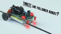
This guide teaches you how to make a zippy little line-following robot. No microcontroller nor any programming is needed, only basic electronics!
Looking to turn those inanimate components on your workbench into an amusing experience?
If you are, then you've come to the right place as I welcome you to the realm of tiny robots! In this comprehensive written tutorial, I'll guide you on how you can create the tiniest line follower robot without the need for an Arduino board or any other microcontroller. A simple robot you can assemble for under $10 based on an LM358 Op Amp Comparator IC, Photoresistors, and other common components it uses for its line detection and following abilities. Dive into understanding the intricacies of crafting your very own electronic robot car that effortlessly follows almost any size line with precision. Whether you're a seasoned maker or just starting with electronics, my step-by-step instructions cater to any maker immersed in creation. Join us in this hands-on adventure and witness the magic of bringing your miniature robot to life.
How it works (The Breakdown):
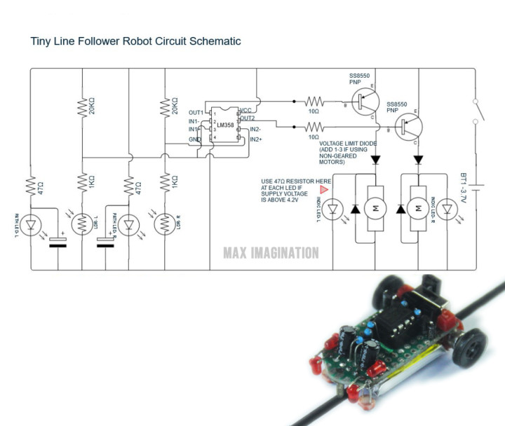
This tiny line-following robot solely relies on a small lithium cell for powering the motors and all other small components on board. The light from the powered LEDs pointing down at the front of the robot is reflected from the surface onto two photoresistors also facing downward receiving either a higher or lower amount of light depending on whether the surface present is black (the line) or white (area surrounding the line). The amount of light received by the two sensors affects their resistance value independently which is also varying their signal voltage that’s constantly being compared VERY quickly by each Operational Amplifier within the LM358 dual Op Amp Comparator IC, the robot’s decision-making chip. The comparator will have the Op Amp with the higher voltage or inversely, lower resistance photoresistor (AKA whichever sensor gets more light) to output a current to the BJT transistor that drives that side motor (left or right drive motor), pushing the robot back on the line while going forward. The potentiometers (in this case = 20KΩ fixed resistors) which are linked with the photoresistors in a voltage divider circuit, can be tuned to adjust the sensitivity of the sensor array. Only one motor at a time is in use to drive the robot forward which allows it to continuously check if it’s staying on track. The two capacitors at the front are purely for creating a smoother transition with reduced glitching of power sent to either of the two motors + indicating LEDs.
With this rather simple decision-making circuit, the robot can detect and follow lines with ease.
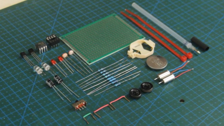
Right before we begin with this project, let's quickly go over the electronic components and other parts we will need.
Pro tip: You can find most of these parts in old or broken appliances you may already have at home - this is a good time for some component salvaging! Unless you prefer the convenience of ordering the parts, you may prefer to obtain them through my affiliate links below.
Components and Parts
- (x1) LM358 Op Amp Comparator - https://amzn.to/3SJnidL
- (x1) 8-pin DIP IC base - https://amzn.to/3T2aTTR
- (x2) SS8550 (PNP) Transistor - https://amzn.to/3OZKF1W
- (x2) Photoresistor (LDR) - https://amzn.to/49zjP8z
- (x4) Round LED (3mm) - https://amzn.to/3UJMDXM
- (x2-6) IN4007 Diode - https://amzn.to/3UJB9Ub
- (x8) 1/4W Resistors from kit (10Ω x2, 51Ω x2, 1KΩ x2, 20KΩ x2) - https://amzn.to/49hHLh4
- (x2) 100µF Capacitor - https://amzn.to/48g2kJf
- (x1) Micro slide switch (SPDT) - https://amzn.to/3wrbOnK
- (x2) Coreless motor (6x12 mm) - https://amzn.to/3RKxl1Y
- (10cm) 30AWG Silicone electrical wire - https://amzn.to/3TO9HUJ
- (x1) PCB Prototype board - https://amzn.to/3S42bE6
- (x2) Mini zip-ties - https://amzn.to/47iiCRD
- (x2 sizes) Heat-shrink wrap tube - https://amzn.to/3UDBMyB
- (x1) Ball point piece from pen - https://amzn.to/3I2VRH1
- (x2) Sewing buttons - https://amzn.to/49A5Uiw
- (x1) LiPo Cell Battery (250mAh 3.7V) - https://amzn.to/3wlpj8E
1. Cutting the PCB to Shape
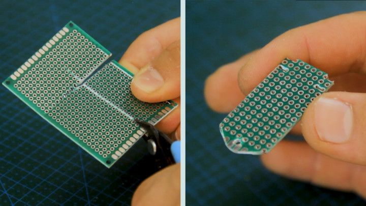
Let’s begin by carefully cutting a perforated prototyping circuit board to the desired shape for your tiny line follower robot's chassis along with custom holes to hold the coreless motors and a ballpoint pen tip as the front caster ball. Following the reference images will ensure we get precise cutouts to accommodate all components and create a sturdy base for your robot.
2. Circuit Diagram
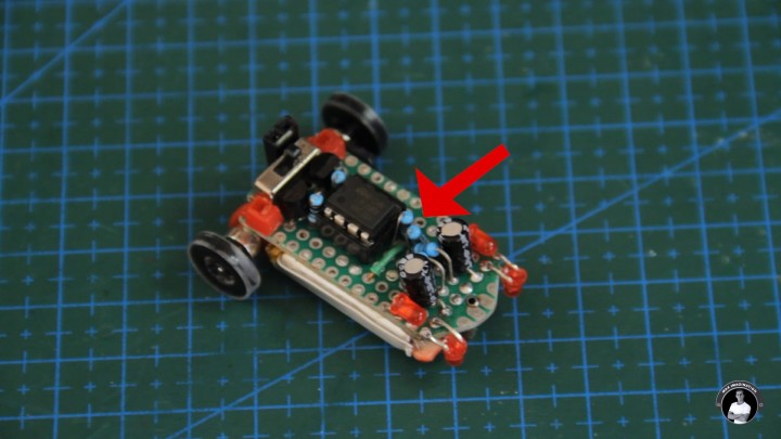
3. Component Placement
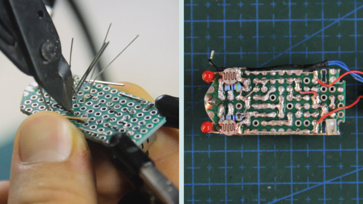
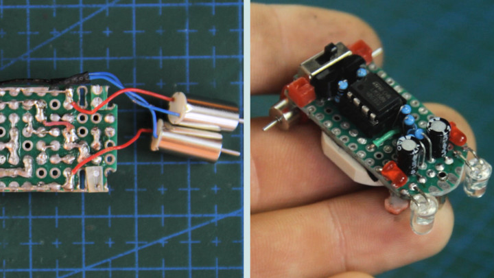
Now we begin inserting most of the components into the board that lay on top in a dense space including the LM358 comparator and its DIP IC base, x2 BC547 transistors, x6 resistors, x2 capacitors, x2 LEDs for turning indication, and a tiny power switch on the rear side according the the diagram. The pins from the underside get bent to keep the components from falling off when getting soldered. Consider both functionality and aesthetics for an efficient and visually appealing layout. For the best outcome with your robot, place components as shown on the circuit board.
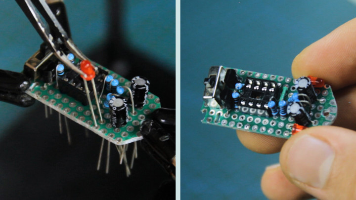
With the component pins bent in all sorts of different ways to keep them on the board, we’ll further bend them to align with the necessary paths the connections need to take like in the Circuit Diagram. From here, it’s as easy as soldering them. At this point it's super easy to overlook a connection or two, so it’s a good practice to keep both the diagram handy and my own board soldering for reference when making connections.
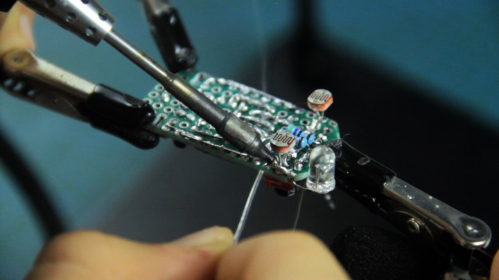
Moving on to the underside of the robot, at the front is where we install components for line detection - the two photoresistors (LDR) and LEDs. We’ll solder them in place according to how they connect up in the diagram. The LEDs’ job is to light the path ahead and the LDRs on each side pick up on a certain amount of that reflected light based on the lightness of a surface the robot is on. The LEDs for lighting the way can either be infrared or standard LEDs - choose the color red for best results. Additionally, soldering appropriate current limiting resistors is required to avoid burning the LEDs - I used two 51-Ohm resistors.
Now we secure the power source for the tiny line follower robot by mounting a 3V coin-cell battery (holder) onto the underside of the chassis ensuring it doesn’t interfere with other components or impede the movement of the coreless motors. Consider the overall balance and weight distribution to ensure stability during operation. Choose a suitable battery based on the power requirements of your components. Consider factors such as voltage, capacity, and size to meet the energy demands of your robot. Connect the battery according to the power input of the circuit which is the VCC and GND, that can be found on separate ends of the circuit. Double-check the polarity to avoid any potential damage to the components. Designing or finding such a mount that allows easy access to the battery for replacement or recharging will ensure the longevity and sustainability of your tiny line follower robot. As a better alternative, I recommend using a LiPo cell for the robot as it’s rechargeable and gives it ample voltage to move it forward.
Additionally, let’s also give our robot a smoother driving experience with a custom caster wheel, a ballpoint pen tip pulled off for the front roller - soldered with tin to the hole in the circuit board. Be sure to select one that is dry from ink, preferably from an old/used pen.
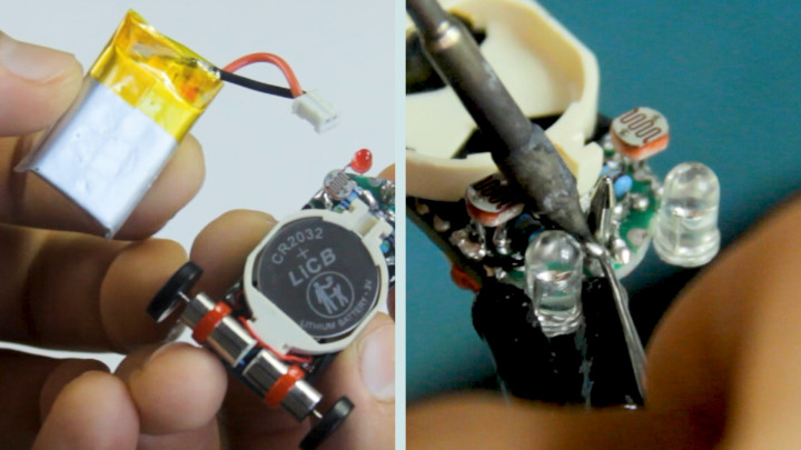
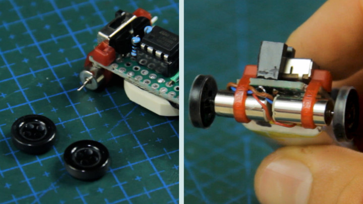
We’ll mount the 6x12-millimeter coreless motors onto the chassis each with a small zip-tie through the circuit board, securing them in place. Afterwards, the motor’s can be connected to the GND track of the circuit and collector pins of the two PNP transistors with any excess motor wires tucked in under the battery. Optionally, Schottky diodes like the IN4007 can be added between the transistor collector pins and the connecting motor wires to reduce voltage to the individual motors if the robot moves too quickly along the line. These motors drive the wheels of your robot, enabling it to follow the designated path thanks to the inputs from the photoresistor sensor array.
You read that right! We’ll be using a couple of your everyday shirt buttons from an old piece of clothing or sewing kit and convert them into wheels for the robot.
Using a screwdriver bit from a kit that’s 0.5-1mm in diameter will normally do the trick in drilling a tiny hole smack in the center of each button while avoiding poking into the 4 other thread holes. Ensure the created holes are small enough to make a tight fit between the buttons and motor shafts. For best luck at the fidgety process of drilling these holes without damaging the button, lightly tap at the center with a sharper object to create a center punch dip. Once mounted onto each motor shaft, cutting some strips of heat-shrink wrap tube for the wheels will greatly help with grip.
Fine-tune your tiny line follower robot by adjusting sensor positions, tweaking resistor values (The 20K-Ohm resistors can each be replaced for potentiometers) This step ensures optimal performance and responsiveness on various surfaces.
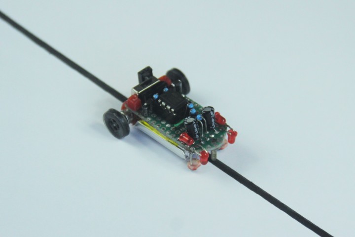
Conclusion
There you have it. If you’ve followed till this point, you've successfully crafted a miniature line follower robot with a unique combination of components, providing a hands-on experience in electronics and robotics. If you’re still reading to make your own one, you may download and follow along with the wiring diagram images linked below.
If you haven’t yet, consider watching the full video tutorial for more in-depth guidance and the robot's driving tests.
Feel free to explore further modifications and unleash your creativity to take this project to new heights!
Want to build a project?
Bring your design to life with the Elektor PCB Service, powered by Eurocircuits. Upload the project files and order professionally manufactured PCBs or assembled boards through a proven European production platform.
Supporting KiCad, Eagle, Gerber, and ODB++ formats, the service is suitable for everything from prototypes and validation builds to series production and volume manufacturing.
Made in Europe. Fast. Reliable. Professional.
Diskussion (5 Kommentare)