Remote 230 VAC switch with state feedback controlled over LoRa intended to be operated over long distance using the LoRaWAN Node Experimental Platform
LoRa-controlled switch with state feedback
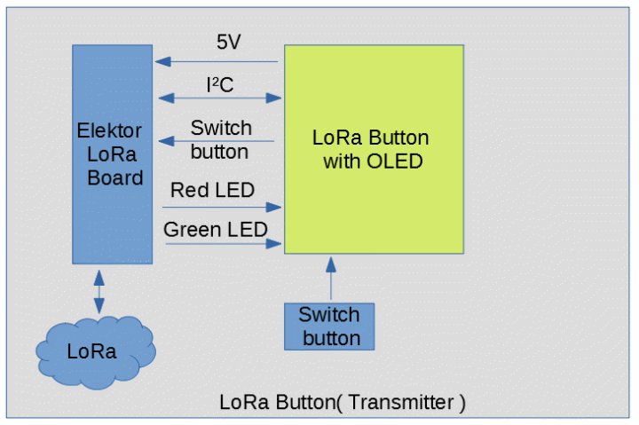
The LoRa-controlled switch with state feedback is based on the LoRaWAN Node Experimental Platform, and shows the versatil use of it. Here we use only the LoRa modulaton for propriatray data exchange, no LoRaWAN included. We have one transmitter and one receiver node involved. The Transmitter uses the same water resistant enclosure as used for the LoRaWAN Node Experimental Platform, a well priced Hammond enclosure, housing two lithum rechargable batteries. Changed from the basic LoRaWAN Node Experimental Platform, we have one switch with led feedback, utilizing the spare GPIOs if the baord.
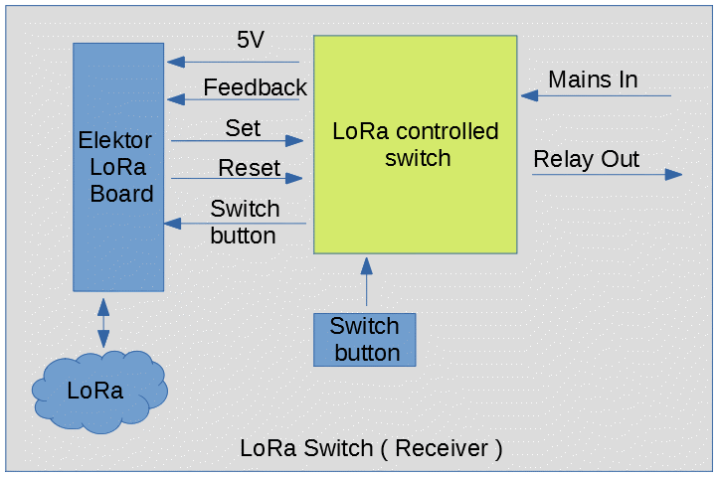
On the switch side we have also the LoRaWAN Node Experimental Platform, this time driving a relay able to switch 115V / 230V
As for the parts requiered you need two LoRa-Nodes, one sitting in housing with the relais and one in the portable switch unit.
Also you need for every part one additional PCB that holds the relay and the 115/230V power supply and the PCB that hold sthe mobile transmitter switch with OLED.
For the relay the used blocks will look likte this:
As you can see the LoRa Node connects to the PCB of the relais. For the button you need a second LoRa Node
[Update 25.10.2019]
Software is transmitting the first time peer to peer. The Hardware for the switch needed to be changed a bit as some pins were connected wrong.
[Update 31.10.2019]
Software has furter improved and the basic feature are ready. The Transmitter as also the part at the relais can be configured with a serial interface and a serial terminal, like the one you have in the arduino ide.
[Update 28.11.2019]
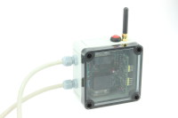
Everthing is put together and working. We got a mobile knob with state feedback form the relais. Here you see the fully assembled Switch in the transparent bluish enclosure from hammond. As power source we used here a USB powerbank we had spare at the Lab. The PCB itself is pertty simple., most of
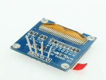
the tricky bits are in the Elektor LoRa Node itself. This PCB just keeps the components in the housing itself. A nice addition ist the FTDI connector on the side o fthe PCB that makes programming a lot simpler. The OLED Shown here is optional ut very usefull.To attach it to the PCB and to fit it into the baord you need to remove some pplastic form the display connector. With some tools remove the surrounding plastic and you will get the bare metal pins that you need to connect to the PCB.
Uplaoding the software can be dne with the Arduino IDE or you can upload the files with the SMT32CubeProgrammer. The only tools requiered for this is a serial to usb- converter running with 3.3V levels.
For the switch the procedure is almost the same, after the finished assembly you will end with a nice little box lite this:
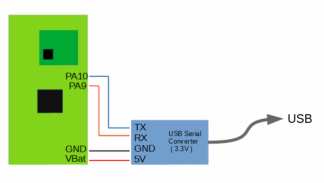
This box will switch the 230 or 110V and report back if 110V / 230V are applied to the output. The assembly is straight forward, you need the Elektor LoRa Node and also the PCBs and parts for the Relais and Switch part. After you put the components together you need tp get the software into both parts. To upload software you only need a 3.3V USB -Serial Cable and connect it to the Elektor LoRa Node like seen here :
Keep the boot button pressed and tick the reset button, like you do on an ESP32, this will set the MCU into the bootloader mode. You can then use the STM32CubePogrammer to upload the Hex files for the firmware to the Chip, or compile the code and uploading it with the arduino IDE.
A simple way is just to grab the hex file and upload it with the STM32CubeProgrammer.
After you put the firmware for each device into its mcu you can configure it with a serial terminal, like the one you find in the arduino ide. As parameter you need to set 115200 baud, 8 databits and 1 stopbit, no parity. As line ending character use Newline.
To make both parts work we need to setup a key to prevent other partys to contorl our relay. To do enter in the terminal "set key 12345678" this will use 12345678 as key. Also you can change the Spreadingfactor (SF ) and the Transmittpower. The Spreadinfactor determines the datarate used by the system, the slower the transmission is the more range you may gain. As startingpoint use SF7 with "set datarate SF7". Also you can change the transmittpower used with "set txpower 2" which sets the output to 2dBm. You can set the output up to 15dBm but be aware that this may collide with the regulator rules for the 868MHz band.
You need to do this setup twice, for the Relais and the Switch. After you have setup both sides you should be go to go.
[ Update 9.3.2020 - How the software works ]
The microcontroller used is a STM32F072, a "small" Cortex-M0 with 64kB Flash and 16kB RAM, which offers more than enough resources for this project. As this type of MCU has been used less in the past projects, here is a short walkthrough how to supply them with software, how to create and upload own software. Finally we want to take a closer look at the functionality of the software inside the switch.
How the binary gets on the controller
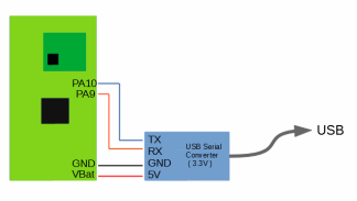
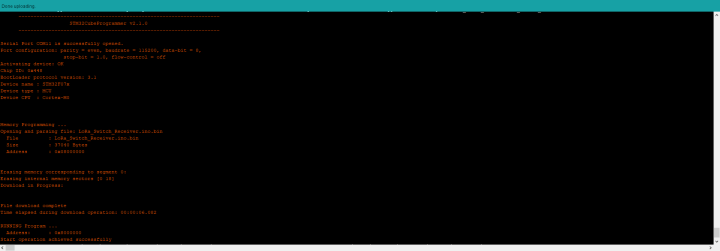
If you only want to program the firmware, you can take the ready binary and program the MCU with the help of the STM32CubeProgammer ( https://www.st.com/en/development-tools/stm32cubeprog.html ). Before starting, the LoRaWAN experimental platform has to be connected to a USB to serial converter as shown in [picture with structure] and the converter has to be plugged into a USB port of the computer. To program the chip it must be in bootloader mode. The MCU can be set to this mode by pressing Boot and pressing Reset briefly. Now the STM32CubeProgammer can be started and the appropriate serial port can be selected.
By pressing Connect a connection to the board is established, and if this was done without errors, the firmware can now be loaded into the chip. For the push button and the relay you have to select the appropriate files. Image Upload Fimrware
After the upload to the MCU is completed, the MCU can be started by briefly pressing the reset button.
The Elektor LoRa board in the Arduino IDE
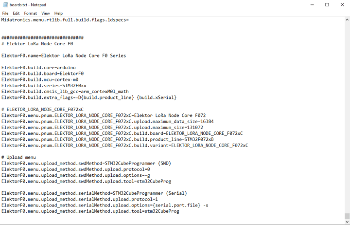
For programming and adapting the source code, however, the familiar and familiar Arduino framework does not have to be abandoned here. The Arduino Core STM32 provides support for a wide range of microcontrollers. This includes the STM32F0 family, but the LoRa Node experimental platform is not yet listed as a supported board. Therefore, a zip file with the board variant must first be downloaded from the Labs site. Here we present the procedure on Windows systems, on Linux systems the folders are slightly different, but the procedure is basically the same. Starting with version 1.7.0 of the STM32 Arduino Core the following directory is opened in the File Explorer " %localappdata%\Arduino15\packages\STM32\hardware\stm32\1.7.0 ". There you have to add the content from the file "Add_To_Board.txt" of the zip file at the end of the "Boards.txt".
Finished modifications
The last step is to copy the folder "ELEKTOR_LORA_NODE_CORE_F072xC" from the zip file in the folder "Variants" and the Ardunio IDE has to be restarted once. Now the "Elektor LoRa Node Core" appears under Boards at the end of the list as selection.
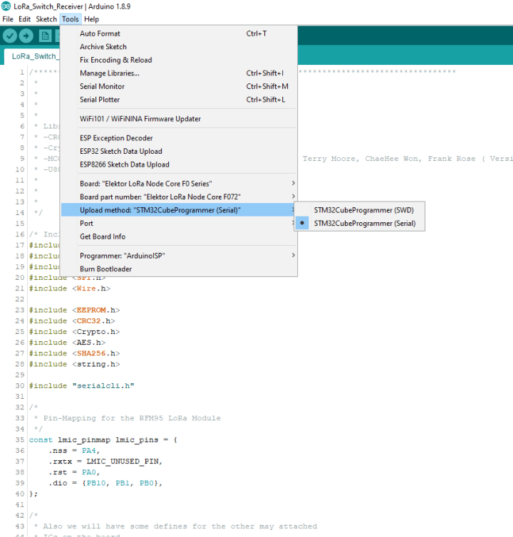
To get the compiled software on the board you have to install the STM32CubeProgammer first. The Arduino IDE will automatically use it for uploading. From now on you can compile the software for the board. To do this, the settings are made as in [Picture with settings]. If you want to compile the source code for the button or the relay you have to install the libraries given in the source code. For the upload, the board must be set to bootloader mode, as already described for the binaries. By uploading the firmware is then transferred to the board.
From keystroke to action
After both the relay and the button are supplied with firmware, the configuration is started. For this purpose the board must be connected to a USB-serial converter as for the upload. Figure XX shows how the connection must be established.
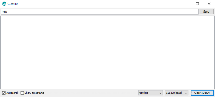
The procedure and the commands are the same for the button and the relay. After connecting and supplying power, the microcontroller starts and the serial terminal can be opened. As parameters 115200 baud and as end of line NewLine have to be set.
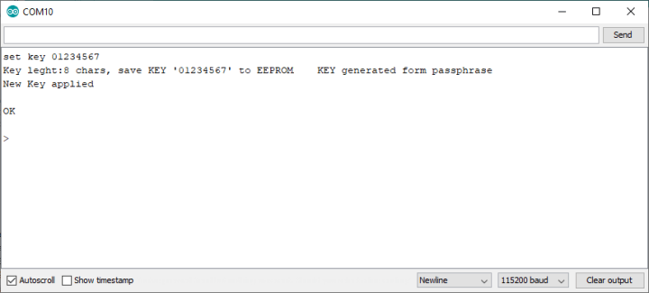
After entering "help" and a click, the output appears as in
To set the transmit power, "set txpower xx" can be used to set and "get txpower" to query. The values specify the output power in dBm. One parameter that must be set equally on both sides is the data rate. In delivery state this is set to SF7. With a "set datarate SF8" the new data rate is SF8. The higher the value, the lower the data rate and higher the range. With SF7 and the txpower of 2 you get a short range which is less than 50 meters.
Currently no key has been entered. This key is used to prevent any other key within range from sending commands to the relay. Similar to WLAN a passphrase is used here, where it is best to take something that is not so easy to guess, things like "01234567" or "abcdefgh" are bad combinations. To take "01234567" as a passphrase you have to enter "set key 01234567".
If both sides are now supplied with the same key, the relay should now react to inputs from the key.
Further commands may be added in the course of new firmware versions.
For signalling, a distinction must be made between the push-button and the relay. The smallest version of the push button has three LEDs, one red, one basic and a blue integrated in the push button. The blue LED indicates the last known state of the relay, if this flashes, there is currently an attempt to communicate between the push-button and the relay. If an error occurs and the push-button has to send data again, the red LED starts flashing and the green LED goes dark. If there is no communication after two new attempts, the red LED lights up permanently.
If the push-button is not used for 60 seconds, it switches to energy-saving mode. Here, all LEDs and any OLEDs are switched off. The MCU is not stopped completely, but runs here only with 125kHz. The MCU still executes code and is not yet in maximum energy saving mode, so the current consumption decreases from 9mA to 2.4mA with OLED. If now the button is pressed for 10 seconds the MCU leaves the energy saving mode and the green LED and the blue one start flashing. The push button now tries to request the current status from the relay. If this fails, the push button goes back into energy saving mode.
The relay is signalled by the onboard LEDs, with the green LED indicating that the relay is ready for operation and the red LED reflecting the current state of the output. If it is red, the consumer behind the relay is switched on.
Behind the scenes of the software
Switching a relay on or off via LoRa radio may sound simple at first, but if the access of strangers is to be made more difficult or even prevented, it becomes more difficult. But first a look at the pure data exchange. The LMIC ( LoraMAC-in-C ) is primarily intended for use in the LoRaWAN, a radio network based on the LoRa radio standard consisting of nodes and gateways, but can also send data directly via LoRa radio to other LoRa receivers. The protocol of the LoRaWAN is ignored and the receiving parameters are adjusted and the packets with the payload are sent directly. Not only are suitable functions provided from the library, but also the time sequence can be controlled by the LMIC.
For the relay the sequence is quite clear, after initializing the components the function rx() is called in setup(). This function sets the LoRa modem into receive mode and additionally sets a timeout in case no data is received within 30 seconds.
The function call expects as parameter the name of the function which should be called when data is received. From this point on the library takes care of controlling the timeout.
If no data is received within 30 seconds the timeout function ensures that the LoRa module is put into the soup end state and then changes directly back into the receive mode. This is to avoid that the modem remains trapped in an intermediate state. The timeout is set to 30 seconds again and the timeout starts from the beginning. But what if data was received?
In this case the function we passed as parameter in rx() is called. This function starts to check the incoming data and if given, execute the command. Beside setting a state for the output of the relay, the actual state can be queried. Later on, the software can be flexibly extended by new commands or even completely different functions can be realized with the hardware.
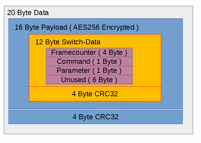
To check the data, first of all the structure and setup should be considered.
The data is packed in several layers, where the inner layer, of which the 16 byte payload is encrypted with AES. After receiving the data, the system first checks if the correct number of bytes has arrived. If this is not the case, the data is discarded and the system switches back to receive mode.
If the correct amount of bytes has arrived, the next step is to compare the checksum (here CRC32) in the packet with the calculated checksum of the packet. If the checksum is not identical, the packet is rejected as defective and switched back to receive mode.
If the data in the packet has arrived correctly according to the checksum, the payload part is then taken and decrypted with the key in the system. AES with 256Bit is used for encryption. After decryption a checksum is calculated over the decrypted data and compared with the contained and decrypted checksum. If the checksums are not equal, the data is discarded, because it seems to have been encrypted with another key.
As a last step the frame counter transmitted in the packet is compared with the internal frame counter. If the transmitted value is equal to the internal expected value, the data is passed on for processing. If the frame counter is not correct, a data packet with the expected frame counter and the command is sent back to the probe with a 100ms delay for synchronization. The request for synchronization runs through the whole process backwards and is structured similar to a confirmation and feedback of a command.
If now all data in the received data are consistent, the data are processed further. The current commands in the packet are NOP ( No Operation ) , SET OUTPUT , GET OUTPUT and SYNC.
If a NOP is sent from the pushbutton to the relay, the receipt of this command is only acknowledged without triggering any further action. GET OUTPUT, as the name suggests, ensures that the current state of the relay is transmitted back to the push-button. With a SET OUTPUT the output of the relay is set to the desired state and after one second the state reached is reported back to the push button.
A special feature is the SYNC command. If the frame counters of the key and the relay do not match anymore, the relay sends back the currently expected value to the key.
The frame counter is used so that packets from third parties cannot be recorded and simply sent out as a repeat.
From password to key
As already mentioned, the data is encrypted with AES (Advanced Encryption Standard) with a key length of 256 bits. AES works block based, i.e. with data of fixed length, in this case 16 Byte ( 128 Bit ). These 16 bytes can be found in the payload, i.e. our user data. These consist of four bytes of CRC32 checksum and 12 bytes of data for command and parameter. This results in the 16 bytes required for a block for encryption. In addition to the data for encryption or decryption, a key is also required. With AES both sides must have the same key for decrypting and encrypting, this is a symmetrical procedure. Another possibility are asymmetric procedures, where a different key is needed for encryption than for decryption, e.g. Ellipcic Curve Cryptography.
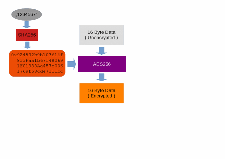
For the AES encryption used here, 256 bit long keys are used, but their Bert is not entered directly by the user. As already mentioned in the introduction, the system uses a "phassphere", a password construct that can consist of several words. To get a key from the passphrase a HASH is used, a mapping of the passphrase to a number. The algorithm used here is SHA256 and returns a 265 bit number, which is suitable as 256 bit AES key. So our key "01234567" becomes the hex number 0x924592b9b103f14f833faafb67f480691f01988aa457c0061769f58cd47311bc, which consists of 32 bytes. These 32 bytes are then used as the key for the AES, which is used to encrypt our 16 bytes of data, i.e. the payload.
However, this structure is not un-hackable, since on the one hand the password is stored in the EEPROM of the microcontroller, and any encryption can be broken with enough effort and by pure trial and error, if the algorithm is known. The encryption process and details can be found in the source code.
Once relay and back
In the following, the communication between button and relay will be shown as an example. The relay is switched on and the same password is assigned to the push-button. In this case, the push-button is disconnected from the power supply and is plugged in. Relay and pushbutton are in mutual radio range.
Push button:
- Initialize hardware.
- Reading the passphrase and generating the AES key
- Set the timer for the energy saving mode to 60 seconds
- Send request for the current status of the relay
- Switching to receive mode
- Set timeout for receiving data to five seconds
Relay:
- Receiving and decrypting the data
- Processing the request and reading the relay status
- Sending the data with 100ms delay
Button:
- Receiving and decoding data
- Reply Process and accept the status
- Cancel receive timeout
- Set timer for the energy saving mode back to 60 seconds
The button is now ready for operation. If the button is not pressed within 60 seconds, the button switches to energy saving mode. First of all, it is assumed that the button is pressed.
push button:
- Pushbutton registered
- New state determined
- Preparing and encrypting data
- Send data
- Timeout for a response Set to 5 seconds
Relay:
- Receive data
- Decrypt and verify data
- Set the relay to the new state
- Wait a second
- Read the current state of the relay
- Preparing and encrypting data
- Reply Send
Button:
- Receive Data
- Checking and decrypting data
- Process response
- Switch off timeout for reception
- Set timeout for the energy saving mode to 60 seconds
If no button is pressed for 60 seconds, the button switches to energy saving mode. All LEDs and the OLED are switched off and the processor clock is reduced to 125kHz.
This would mean that the normal conditions for the operation of the button would have been run through once. For further details of the software and the serial console the source code is available.
Das Elektor Magazine gehört seit 65 Jahren zu den führenden Informationsquellen für Elektronikingenieure, Entwickler, Start-ups und Unternehmen. Unser Magazin wird von einer aktiven Community aus Elektronikingenieuren – von Studenten bis zu Profis – getragen, die mit Leidenschaft innovative Ideen entwickeln und teilen.
Für diese veröffentlichen wir jedes Jahr Hunderte von Beiträgen in Formaten wie Artikeln, Videos, Webinaren und weiteren Lernformaten. Unsere Mission ist es, Wissen auf jede mögliche Weise zu teilen und die Leser mit den neuesten Entwicklungen im Bereich der Elektrotechnik zu inspirieren.
Vielen Dank für Ihre Bewertung!
Kommentar hinzufügen
Vielen Dank für Ihre Bewertung!
Möchten Sie einen Kommentar mit Ihrer Bewertung hinterlassen? Bitte melden Sie sich unten an. Nicht gewünscht? Dann schließen Sie einfach dieses Fenster.


 With some tools remove the surrounding plastic and you will get the bare metal pins that you need to connect to the PCB.
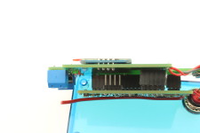

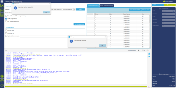
![Figure 10 [Image Upload Fimrware ]](https://cdn.xingosoftware.com/elektor/images/fetch/dpr_1,w_720/https%3A%2F%2Fwww.elektormagazine.de%2Fassets%2Fupload%2Fimages%2F42%2F20200309074456_Bild10.PNG)


Diskussion (10 Kommentare)