
JACK IN & JACK OUT
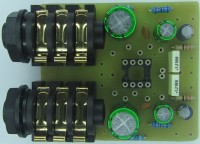
2 jacks, 1 double operational amp and lots of possibilities.Enough to make an experimental plate
The initial basis of this project was to make an impedance adapter for the input and output of a compressor. The operational amplifier was therefore mounted in buffer mode.
Version 2 allowed me to give gain to each element of the NE5532 and to use the function of the jack with cut-off by 3 points (A, 0, B)
Let's analyze the diagrams:
C1, C3, C4, C6 are the connection capacitors which prevent any DC components from disturbing the operation of the op amp. Everyone is free to place them or not when you know what is upstream and downstream of the assembly.
R1 & R6 set the input impedance.
R5 & R10 set the output resistor.
R4 & R9 are pull down resistors.
The gain is calculated like this: A1= 1 + R2/R3 and A2= 1 + R7/R8
R11, C7, C8 and R12, C9, C10 constitute the filtering and decoupling of the NE5532
Let's explore the possibilities:
1 / BUFFERS:
In this version 2, I remove R2, R3, C2 as well as R7, R8, C5 then I place straps in place of R2 & R7
2 / INSTRUMENT AMP:
Here is the role of the cut-off jack with the A (Strap between A & 0). Who says instrument rhymes with high input impedance. In the absence of a jack inserted in J1, the input is grounded which avoids hum & buzz. R1 can be replaced by values higher than 100K (see instrument characteristics) and C1 can go down to 0.47 µF. If R3 =1K and R2 =47K, the gain will be 20 log 1+47/1 = 33dB. Let's make R2 variable for different gains by replacing it with a potentiometer. We can make the junction between the output of R5 & the input of C4 and mount OP2 in buffer to output in low impedance on J2. Here we are in the presence of an active DI BOX.
3/ ACTIVE INSERT:
Here is the role of the cut-off jack with the B (Strap between A & B)
In this case, J2 is SEND and J1 is RECEIVE.
In this version 3, I remove R2, R3, C2 as well as R7, R8, C5 then I place straps in place of R2 & R7. Let's connect a microphone preamp to the input of C4, we will output the signal on J2 to supply a series effect and its return will be on J1. In the absence of a jack inserted in J1, the signal is looped and is recovered at the output of R5
Simple and easy to implement, this montage can really serve as an experimental base for your audio projects.
4 / AUDIO LEVEL CONVERTER
You want to go from a CINCH level (250 mV) to a Jack line level (775 mV), you will need +/- a gain of 3 (+ 10 dB) or the following calculation:
G = 1+ CPR / R feet.
With RCR =22K & R Feet = 10K, we have the solution.
Want to build a project?
Bring your design to life with the Elektor PCB Service, powered by Eurocircuits. Upload the project files and order professionally manufactured PCBs or assembled boards through a proven European production platform.
Supporting KiCad, Eagle, Gerber, and ODB++ formats, the service is suitable for everything from prototypes and validation builds to series production and volume manufacturing.
Made in Europe. Fast. Reliable. Professional.
Updates des Autors