
Electronic candle
English: This simple circuit is responsible for simulating a small flame in a LED, thereby simulating the flame of a candle without using real fire and using just two AA or AAA batteries, so being a safer candle thus avoiding the real the risk of any fire if we forget to turn it off.
English:
This simple circuit is responsible for simulating a small flame in a LED, thereby simulating the flame of a candle without using real fire and using just two AA or AAA batteries, so being a safer candle thus avoiding the real the risk of any fire if we forget to turn it off.
The design consists of a small PIC12F675 microcontroller programmed to generate a PWM signal which is injected to the LED, thereby to vary the duty cycle of the signal to vary the intensity of the LED will emit light. To simulate our flame will the PWM randomly varie sign using a digital technique to generate random values known as a pseudo-random bit sequence (PRBS), each signal change occurs in a period small enough to make you reach noting the change in LED brightness, thus the light intensity vary randomly simulating lighting changes that occur in an actual flame when moving with the wind.
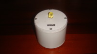
Being such a simple model does not know a PCB one if not mount it on a universal PCB, using a piece of PVC pipe small with two covers acrylic to send to do, manufactures a small candle (As seen in the pictures ). In my case using a big yellow LED, but nothing prevents you to use LEDs of other colors like orange (which also simulates very well a flame), or perhaps in some other different from a normal call and make a special candle color. However, because the light intensity and the voltage drop of an LED varies with the model, you must set the minimum and maximum levels of the PWM signal for the LED lights to a minimum with the minimum value generated by the PRBS (0), and the maximum to the maximum value that is generated (255), can be supported using a simple PWM generator to know the times and adjust the settings within the program to get the proper range, also if necessary adjust the value protection resistor LED (R1), to adjust the light intensity to a proper value.
Also you can practice with to create other forms of simulation, eg using an interface suitable power, can simulate the flame in a lamp power to 110/220V, an ignition system to fire off blown, among other ideas.
Video: http://youtu.be/JKh8L83FJV8
Español: Este sencillo circuito se encarga de simular una llama pequeña en un LED, simulando de esta forma la llama de una vela sin utilizar fuego de verdad y utilizando tan solo dos pilas AA o AAA, siendo asi una vela mas segura que las verdaderas evitando de esta forma el riesgo de algun incendio en caso que nos olvidemos de apagarla.
El diseño consiste en un pequeño microcontrolador PIC12F675 programado para generar una señal PWM que se inyectara al LED, de esta forma al variar el ciclo de trabajo de la señal variara la intensidad de luz que emitira el LED. Para simular nuestra llama haremos que la señal PWM varie aleatoriamente, utilizando una tecnica digital para generar valores aleatorios conocida como pseudo-random bit sequence (PRBS), cada cambio en la señal se produce en un periodo lo suficientemente pequeño como para que se alcance a notar en el LED el cambio de luminosidad, de esta forma la intensidad de luz variara de manera aleatoria simulando los cambios de luz que se producen en una llama verdadera cuando se mueve a causa del viento.
Por ser un modelo tan sencillo no realize PCB alguno si no que lo monte sobre una placa universal, y utilizando un pedazo de tubo PVC pequeño junto con dos tapas de acrilico que mande a hacer, fabrique una pequeña vela (Como se observa en las fotografias). En mi caso utilice un LED amarillo grande, pero nada impide que pueda utilizar LED's de otros colores como el naranja (Que tambien simula muy bien una llama), o quizas de algun otro color distinto al de una llama normal y hacer una vela especial. Sin embargo, debido a que la intensidad de luz y la caida de voltaje en un LED varia segun el modelo, debe ajustar los niveles minimos y maximos de la señal PWM para que el LED se ilumine al minimo con el valor minimo que genere el PRBS (0), y al maximo con el valor maximo que se genere (255), puede apoyarse utilizando un sencillo generador de PWM para saber los tiempos y ajustar los valores dentro del programa para conseguir el intervalo apropiado, tambien de ser necesario ajuste el valor de la resistencia de proteccion del LED (R1), para ajustar la intensidad de luz a un valor adecuado.
Tambien pueden practicar con el para crear otras formas de simulacion, por ejemplo utilizando una interface de potencia adecuada, pueden simular la llama en una lampara de potencia a 110/220V, un sistema de encendido con fuego y apagado con soplado, entre otras ideas.
Video: http://youtu.be/JKh8L83FJV8
HUGO Tecnologia
https://www.facebook.com/hugotecnologia
Diskussion (1 Kommentar)