
digital FORMANT synthesizer (d-FORMANT) [130374]
FORMANT is an analog monophonic synthesizer published in the 70’s from Elektor magazine. It has a modular structure that allows it to be constructed step-by-step and expanded at will. It can be built at home and it is an excellent model to fully understand the operation of subtractive-type synthesizers.
FORMANT is an analog monophonic synthesizer published in the 70’s from Elektor magazine. It has a modular structure that allows it to be constructed step-by-step and expanded at will. It can be built at home and it is an excellent model to fully understand the operation of subtractive-type synthesizers.
This project presents a completely digital counterpart of the original FORMANT; let’s call it d-FORMANT. The basic idea is to replace the analog voltage that represents a signal with a digital 16-bits serial signal. The modular structure is fully maintained. Even the patching capabilities of the original FORMANT has been kept and the user can connect and disconnect cables while the d-FORMANT is working. All the knobs and switches can be implemented, although this first version of the d-FORMANT has a much simpler (and cheaper) user interface: A LCD, some buttons and a rotary encoder are enough to do the jobs of all the potentiometers and switches of the original FORMANT. The keyboard can be any MIDI device that sends simple “note on” and “note off” commands. The digital output passes through a DAC to produce an analog out.
Implementation
All parts except the DAC are through-hole. This makes the construction of the various modules very easy. The author has handled used the DAC also by hand, making a simple “adaptor”. All modules have been constructed in prototyping boards.
Further work
The design keeps its modular structure allowing expansion and modification. For example, a REVERB module, or a QUITAR FUZZY BOX can be added.The user interface is very simple. However, its output is in RS232-type format. A possible enhancement could be to implement a user interface that is easier to use, either in hardware, or in software running on another machine (a tablet for example). The obvious benefit of the digital nature of the synthesizer is the existence of already stored sets of parameters.
The synthesizer is monophonic; however it is easier to expand the digital than the analog FORMANT to produce a polyphonic model.
The final design is cheap enough to implement it “just for fun”, and capable enough to have fun!
Update 16 May 2013:
-- I have added a zip file containing all the kicad schematics.
-- During the past two weeks, I have noticed a problem with the DAC: when the VCO's signal is square or saw, many erratic frequencies are produced in an audible level (It is also audible in the two mp3 samples). I use the "Visual Analyser" in my PC, and I can see a spectrum that reminds me intermodulation !!! The problem does not apear in pure sinus waves ! (although some low level bad frequencies apear when the produced frequency is over 10 KHz). I have perfomed many modifications to the DAC circuit and to the DAC's MCU, with no result ! I cannot decide if the problem comes from the way I produce and send the signals to the DAC, or from the DAC. I changed the signal to the DAC to I2S-format ==> no change. I will try to drive the DAC in 24-bits format (of course the rest of the d-FORMANT will continue to work in 16-bits). The next step is to use a different DAC !
So, don't make a PCB for the DAC, as there may be modifications !! (On the other side, I don't know if the problem arises from the fact that I have soldered the DAC chip "on the air").
Update 27 May 2013:
The problem is not in the DAC or in the driving MCU: the problem comes from the theory and appears to any Direct Synthesis circuit that produces waves with overtones. It is a classical "alias" problem which means it is inherent to the method and it involves the sampling frequency. I am currently reading the bibliography to find some way to overcome it: it apears that the best method is to implement a VCO that doesn't produce overtone frequencies over 20KHz.
Update 15 June 2013:
I changed the VCO code. I also updated the MP3 files (piano, miaou). The new version of the VCO is now "cleaner" in the square and saw waves. More information is given at the VCO section that has been updated too.
The MP3 files are produced using the following parameters:
1) piano-like:
one VCO: square wave, PM=8.5, PWM=1.0.
LFO (out1) feeds VCO's PWM
LFO: f1=5.0, wave = triangle
VCF12: ENV=0, Oct=0.5, Q=0
ADSR2 (for VCA): AD mode, A=0.1, D=4.6
2) miaou:
One VCO: square wave, PW = 7.0, FMin=2.5 (FM gets input from ADSR1 out)
VCF12: ENV=10, Oct=-5.0
ADSR1 (for VCF12): AD mode, A=1.5, D=3.5
ADSR2 (for VCA): ADSR mode, A=0.1, S=10
keyboard: Portamento=4.0
Update 23 Oct 2013:
I have uploaded a new version of the "keyboard" code. This version (2.01) lets the user select between "lower note" and "last note" when more than one keys are pressed simultaneously. It also lets the user decide if pressing a second key re-trigers the ADSR, or does nothing. More information (and the new code) is provided in the updated "keyboard module" section.
I have also updated the code for the "control" module to version 2.01. It supports the above enhancements of the "keyboard" module, and also improves the operation of the rotary encoder. The new code is provided in the "control module" section.
Update 25 Jan 2014:
I am trying to explain the code running in the MCUs. I uploaded file "dFORMANT-assembly" that sketches the structure of the code that is common to all modules (except module CONTROL). The description is based on the code for VCO moule that has been updated.
I intent to "clean up" and update the code of all modules to conform to this description.
Update 28 June 2014:
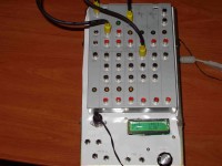
I have added a "front panel" for the VCO. It is described into a separate contribution. I tried to upload a video showing it operate in parallel with the main control but I failed, so I uploaded only a photo of it.
For the moment, this "secondary controller" is implemented into an mbed module but I intent to use a PIC24FJ. The secondary controller uses a separate 3.3V power supply.
Update 15 Oct 2014:
I have added a microSD card interface to the CONTROL module in order to read and store sets of parameters. Tis requires an upgrade of the CONTROL module's MCU to the 64Kbyte version (PIC24FJ64GA002). The new code, schematic and documentation (V2.4) is in the respective contribution "d-FORMANT control (User Interface)"
Update 6 Feb 2015
I have been working on this project for more than four (4) years (I posted it in Elektor-Labs about two years ago). During this time, many ideas have come in mind (and if I dig in my papers, I’ll find notes for the most of them). At this moment, I have settled to a set of things that I would like to implement. Actually, I have already started to implement some of them. But it seems that they require a great amount of my time, and I’m afraid that it will take years to implement all my thoughts!
So, I decided to write down a brief description of my ideas (more like a whish-list than a technical document).
Part A: HARDWARE
- Problem: Each module has a set of inputs and outputs that carry the serial “data” signal. Part of the interconnection between the modules is fixed and the rest of it is manually “patched” by the user through cables. (I was very proud for this ability: you could patch digital signals in a way similar to analog signals!) However, if you want to store the settings of all the controls for a new voice that you have created, you won’t be able to store the cable patching! And more, you won’t be able to easily reset the synthesizer to your new voice, as you will have to make all the cable connections manually. So, the interconnections must be automated in some way.
Solution: Each module consists of only one (1) MCU. All modules are “stacked” (just like Arduino’s shields), so all RB16 pins are joined together, all RB15 pins are joined together, and so on. Each module has one (1) output. The output of each module is presented in a different pin. So, each module can “listen” to all other modules’ output! The control module directs each module to assign its input(s) to specific pins. For example: the LFO has its output at RB10, and we want to use it to modulate the VCO1. The FM input of the VCO1 must be assigned to RB10.
All modules with two or less inputs can be directly implemented in this schema. For the rest modules I would like to have MCUs with more than two SPIs. A possible solution is the PIC24FJ64GA202, as it has three SPIs (and is in a SPDIP-28 package.) Another solution would be to use QFP-packaged chips that have four SPIs. Of-course there is a need to implement some “mixer” modules, for example to feed the VCFs. (There are some adaptor PCBs that can “convert” QFP to 2.54mm spaced pins: they are perfect for this purpose as nothing else is required from a PCB for this design!)
A potential problem could be the maximum number of chips that can be “paralleled”. Unfortunately, I can’t find the input capacitance of the MCUs’ pins in order to estimate this number, so I have to try it in real! (I hope that 10 to 15 modules can be used). Anyway, the complete synthesizer can be split into three major parts: VCOs, VCFs, VCAs, so 10 modules for each part (for ADSRs, LFOs, etc) is a good number!
The control module must implement more “parameters” that correspond to the input selectors for each module.
- Problem: The initial built-in interface of the control module is not very user friendly. I have enhanced the control module with the ability to receive MIDI CC commands for use with commercial products (Have to thank Clements for his suggestion). I have also posted another board that has separate controls for the VCO. I intended to build a separate board for each module, so that the final construction would resemble the original FORMANT’s front panel. I have to say that I abandoned this project, as it requires too much effort, too much time, too much space, and if I need an extra module (e.g. one more ADSR), I should build a new panel for each extra module.
Solution: I have started building a “general” front panel, with eight (8) rotary encoders for the parameters and three (3) rotary encoders to select the input configuration (as described above). Each encoder has (of course) its led-ring (more or less like the Cocorico project) and an 8-character display that shows its function (i.e. the label of the control). When the user rotates an encoder (or just pushes its button), the 8-character display shows the real value of the parameter for 8 seconds or so.
The 3 “input set” encoders can have their own 8-character displays, or a 4-line LCD.
The 8-character display can be implemented either with LCD, with dot-matrix led modules (vary expensive), or with 16-segment LED displays (which I prefer most!)
The complete panel has one MCU to control everything, and communicated with the “control” module through I2C. This will enable more than one panel to be used at the same time (if one wants it).
- Problem: I would like to have a tool to check the signal at the output of the modules
Solution: An MCU with a LCD module can “listen” to the data stream and display minimum and maximum values like a VU-meter. Or, it can display even the spectrum of the signal!
Another solution could be to stream the data to a PC via a USB (the MBED platform seems a good candidate)
Part B: SOFTWARE
- Problem: The code of all modules (except the control module) is written in assembly. I admit that I really enjoy writing assembly! However, some problems arise from the use of assembly: a) not many people share my preference on this language, and even less are willing to read someone else’s code, just to make some modifications. b) Other microcontrollers could be used -for example the LPC800 series from NXP is a good candidate- but this would require a total re-writing of the code. So, I guess C would be a better option.
Solution: The code of some modules can be re-written in C, for example the code for LFO or ADSR.
Some modules really use all the computing power of the MCU (for example the VCF24), so the transition to C may not succeed. Perhaps an optimizing compiler may produce fast enough code, but I haven’t access to such a tool, and I don’t think that the free tools from Microchip can achieve the required optimization (although I can try it!). A possible solution would be to use a faster MCU from the same family.
- Problem: The VCO has some alias problems. The methods I use are fast but they do not produce very clean signals. There are some methods like BLIP and BLEP, but I am not sure that I fully understand them!
Solution: I have developed a novel method (that has the same root as the BLEP method) which works for any “geometrical” signal (I mean any signal that can be represented as a series of lines: square, triangle, saw, or even trapezoid-if it has any meaning). My method uses a large ROM table, so it requires large amount of flash memory. Good candidates are some chips with 256 or 512 Kbytes of memory.
- Problem: New modules could be useful, for example echo, samplers, et.c.
Solution: Most of the new modules do not require any new hardware, just new code. An exception is the “echo” module that requires a large amount or RAM.
Part C: HARDWARE & SOFTWARE !
- Problem: All the methods that eliminate alias in the VCOs assume that a constant (or slow varying) frequency is produced. These are good for Frequency Modulation by an LFO, but are not adequate for “real” FM with an audible signal.
Solution: All the VCOs work in a really high rate (typically 1000 X 48KHz = 48MHz, target will be 10000X48KHz = 480MHz). A strong down-sampling FIR filter is used at the final output of the VCO to cut all the frequencies over 48 KHz and resample the signal in 48KHz.
This solution cannot be implemented in a processor, but FPGAs are just suited for this kind of applications. Well, FPGAs are not the easiest parts to deal with, both physically (they are usually produced in BGA packages) and logically (an efficient implementation cannot be made with just a compilation from C). But they can run REALLY FAST.
Update, 7-Mar-2015
I discovered that there is a major bug that affects all modules (except the control module): All the modules use the Serial Peripheral Interfaces (SPIs) in SLAVE mode (they get the clock externally). The input data are latched at the rising edge of the CLOCK signal, and the output data change at the falling edge of the CLOCK signal. When the SPIs are configured for this mode of operation, the data-sheets say that we have to use the "Slave Select" input (SS input) in order to get the SPI module work properly. The "Slave Select" is a feature that is not used in dFORMANT, so in my implementation, I just ignored this point of the data-sheet !
However, everything worked fine. Until the day I bought a couple of new PIC24FJ64GA002 chips: the SPIs went out of sync. (datasheets were right)
So, why do the first modules work? (it's not one chip or two, there are 17 MCUs, all working perfectly). The answer is in the bugs inside the chips: All the chips I had so far were of "silicon version" Rev A3 or A4. These chips just do not recognize the "Slave Select" signal, so it is just like I had a SS pin tied to ground. This "silicon errata" has been corrected in next version of chips, and my new MCUs (Rev B5) recognize the SS signal, and require its use for proper operation of the SPI.
Solution:
1) configure the SPI with SS enabled (software)
2) map SS input to a pin (software)
3) tie this pin to ground (directly or through a resistor) (hardware)
I have tried it with the LFO code and works O.K. (I guess that this new code will work with Rev A3/4 chips too).
Updates des Autors