
DCF Timecode Visualisation Clock
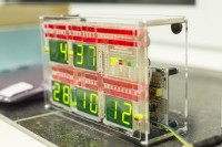
What makes this DCF-Clock different is that it shows the string of incoming bits from a DCF-receiver and their meaning. There are two strings of LEDs above the 7-segment displays for the bits representing the BCD time and date-code. The upper one is filled with the incoming bits from a DCF-receiver representing the code for the next minute.
What makes this DCF-Clock different is that it shows the string of incoming bits from a DCF-receiver and their meaning. There are two strings of LEDs above the 7-segment displays for the bits representing the BCD time and date-code. The upper one is filled with the incoming bits from a DCF-receiver representing the code for the next minute. The lower one represents the bits of the last decoded minute, which is the valid code of the displayed time and date.
The upper LED-pattern is copied into the lower LED string when all 59 bits of a "DCF-telegram" are received and the code is decoded as valid. Then the 7-segment displays shows the new time and the next string of bits are received in the upper LED-string and so on. Additional to the time code there are the three parity bits P1,P2,P3, the day-of-week and the flag-bits at the beginning of the time-code so that the whole 59 bits of a full DCF-telegram can be seen.
A laser-engraved frontpanel in acrylic was created and laser-cut at the Open FabLab of the RWTH University in Aachen. The front-panel shows in plaintext the meaning of the single bits or bit-groups. It can be side-lighted with LEDs so the engraved lines and letters light up.
The clock was presented to the maker-community at the local Dorkbot last week and raised a lot of interest: http://hci.rwth-aachen.de/dorkbot-report55 The continoously upbuilding led-pattern of the DCF-code are fascinating to watch and everybody not familiar with the working of the DCF-code asked about what the changing pattern of LEDs meant.
Except for the attractive look of the clock it can also serve as an educational tool to explain binary data, BCD-code, the concept of parity-check bits and how even complex data can be transported with a speed of only 1 baud (like e.g. the encoded weather-channel data in bits 1-14) in a practical application that everybody knows. So in school, technical exhibitions or in educational institutions it can serve as a means to raise interest in science, engineering etc. Remember that for many people the time-code coming "over the air" is something like black magic to them.
The circuit is based on a totally different kind of clock, namely the wordclock-project of Christian Aschoff, who is co-author of the DCF Visualisation Clock.
http://www.caschoff.de/Bauanleitung_einer_Wortuhr/Willkommen.html
It is based on an ATMega 328 microcontroller programmed with an Arduino sketch. It controls a string of four daisy-chained 74HC595 shift-registers which make a multiplex pattern of 16x16 rows/columns. I had to use this multiplexing "taken to the max" bacause there are all in all 137 LEDs and 80 segments from the 7-segment displays (including decimal points). This way only 3 port-lines from the controller have to be used to control the whole display in a matrix of 14 used rows of the available 16.
Of course the available current source-and sink-capability of the HC595 shift-registers is by far not sufficient to supply the necessary current for the multiplexing. From the datasheets of the used LEDs and 7-segment-displays I decided to set the multiplex-current through each LED/segment to about 100mA which nevertheless makes a total current of up to 1600mA (average is about 400mA). For that purpose the 74HC595 shift-registers of the column-drivers were replaced by the function-equivalent "power shift-registers" TPIC6C595. These are even avaliable in 2 still more power-capable versions as TPIC6B595 and TPIC6A595. So all in all there are only 7 ICs necessary including the MCU, RTC and voltage regulator.
The 74HC595 shift-registers of the row-drivers are followed by logic-level P-channel MOSFETS to deliver the 1.6A peak multiplex current. I choose IRF7104 or IRF7314 which have two MOSFETs in one case. That way only one supply voltage of 5V is needed for the whole circuit. With a low-dropout regulator a 6V/1A wall-socket supply (+ 2.200µF electrolytics for current buffering) are needed.
The ATMega 328 was programmed in BASCOM for this purpose. The ATMega furthermore has a DS1307 or MAX3231 real-time clock on its side for keeping the time in case there is no DCF-reception.
Diskussion (1 Kommentar)