
Universal charger for 3.6V to 22V @ 4A Li-Ion batteries
Battery charger (acid lead, Li-Ion, NiCd, NiMH,...) configurable in voltage and current, especially for portable electric tools
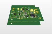
Multi chemistry battery charger for power tools (Li-ion 18v@2A )…and more
Summary
Power tools have become ubiquitous; Individuals and artisans have adopted it in many works because of their autonomy about power supply. But often, if we have several tools and adapted batteries, we usually have only one charger. If it makes the soul in full work, then it's a blow. In addition, if its replacement is no longer possible or with a significant delay and a dissuasive price (this was my case) then we decided to do otherwise. An overview shows me that there are many projects of chargers, sometimes universal "multi chemistery", but they are limited in voltage and unsuitable for power tools ....The idea will be to realize a configurable charger for different types of batteries and voltage.
Analog Device parametric research leads me to the LTC4008 [1], universal battery charger (lead acid, LiFePO4, Li-ion, Li-Polymer, NiCd, NiMH) allowing up to 6 elements Li-Ion and 18 elements Nickel under 4A maximum which covers a large range of batteries. Voltages and currents are adjustable by external resistors; It will therefore be able to respond quickly to the use of Li-ion batteries from 3.6V to 10.8V, 14.4V, 18v and 21.6V. In addition, it has an input for the thermistor of a battery.
Description
Features of charger are 20.8VDC@1.85A . The careful disassembly of the battery reveals 5 Li-Ion elements, a thermistor measured at 10Kohms (CTN) and an internal circuit with a bar graph of 5 LEDs to view the level of the battery voltage.If we estimate 3.6 V per Li-Ion element, then we reach 18 V nominal battery voltage that can be charged up to 4.1 V / 4.2 V per element or 20.5 V to 21 V for battery; this explain why 20.8 V.
What about the LTC4008?
It is a constant voltage, constant current charge controller suitable for Li-Ion batteries. It’s built around a synchronous and constant frequency PWM (pulse width modulation) controller, allowing to adapt the charging current through 2 complementary MOS FETs and a inductor. The charging current is regulated by 2 resistors Rsense and Rprog and it is continuously monitored by the voltage present across Rprog; this is used in particular for the detection of C / 10 when VRprog equals 400mv.The end of charge voltage called floating final voltage Vfloat, will be defined by a precision divider bridge connected to an internal precision comparator (1.28V). This acts on the PWM controller to adapt the charging current.
A thermistor (CTN) continuously monitors the temperature of the battery; if it increases dangerously, the charge stops and resumes when the battery temperature returns within safe limits. This detection circuit is adjustable according to the value of the thermistor but can be inhibited in the absence of thermal protection battery
Four output indicators make it possible to follow the progress of the charging cycle.
The "ACP" output is activated when the normal charging conditions are met, that is, the supply voltage is greater than the battery voltage and there is no battery overheating.
The "Icl" output is activated when the load current is reduced by limiting the input current
When the battery is fully charged, a "/ Flag" indicator indicates that the current reaches 10% of the charging current.
Finally, if the battery overheats, the "/ Fault" output is activated and the charging cycle stops.
Design
This is facilitated with the diagram of the evaluation board proposed by Analog Device integrating the LTC4006 (lower performance) and a very complete datasheet.For this project of charger 18V @ 1500mA, one will choose the following parameters:
- An end of charge voltage Vfloat = 20.54V which will be defined by the divider bridge formed of R8 = 174K 1% and R9 = 10.7K 1%
- The formula given by the manufacturer for the calculation of the load current, sets a constant value for Rprog at 26.7K 1% and a value for Rsense calculated at 0.13 ohm 1%.
- The value of the inductor here 56 µH / 2 A is calculated for DCIN greater than 20 V and Ich = 0.75 A. The manufacturer gives an abacus for some other values of voltages and currents.
- The DCIN voltage is supplied by a switching power supply 24 VDC @ 1.9 A which is more than enough for this configuration: there will never be any current limitation of the power supply below the 0.67A requested. Nevertheless, I will set a limitation of 1 A with
- For tantalum output capacitors (10 µF), the manufacturer recommends the low ESR KEMET T495 series, "Surge Robust" for high current withstand and surges when connecting the power supply and the battery to the charger. I also used non-polarized capacitors and it works properly.
The routing of the circuit is more delicate. It is recommended to respect a dozen points, including the arrangement of certain components in relation to each other, the diameter of the vias for the double face, etc.
Assembly
The old circuit of the battery charger has been removed to leave room for switching power supply of 24V@1.9A juxtaposing the new card cut off according to the dimensions of the case.The charger was originally equipped with 2 LEDs, green for charging and red for overheating.
I took these lights by connecting them to ACP and FAULT and adding a third yellow light to signal the end of charge (Flag).
The board is issued from V.3 schematics (with 3 LED indicators)
V.4 schematics add a fourth LED indicator ICL, if you need...
18 V battery simulator
A dual 0-30 V @ 3 A power supply, with current limiting display is a good idea.One of the channels (1) will supply the electronic board for setting DCIN while the other channel (2) will act as a Li-ion battery simulator. This solution is offered by Analog Device to perform measurements on a 4.2 V charger evaluation board. [2]
To adapt to the project, I use a 20 ohm 40 W power resistor instead of 2 ohm 10 W (preload) between the board and the simulator (2); the serie resistor (0.1ohm 1%) is useless because the lch current is directly read on the channel (1) V2
This method allows to look at the behavior of the charger by varying each of the two voltages. Thus, it is possible to accurately measure the Icl indicators thresholds by limiting the current of the channel (1) or the Flag indicator by increasing the voltage of the channel (2) or else to observe the value of the current of load during the cycle or adjust it by modifying Rsens and Rprog.
Once the correct parameters are obtained, connect the 18 V Li-Ion battery previously discharged to 15V. The load curve shows an increasing voltage, at constant current, up to the floating voltage. At this point the charger maintains this voltage by decreasing the current. When the current reaches 10% of Imax, the flag indicator turns on. The battery is charged!
! As in all electrical projects, it is important to take all necessary safety measures to protect yourself from any electrical injuries when using electrical line 230 VAC.
links
[1] https://www.analog.com/en/products/ltc4008.html#product-overview[2] https://www.analog.com/media/en/dsp-documentation/evaluation-kit-manuals/dc370A.pdf
Want to build a project?
Bring your design to life with the Elektor PCB Service, powered by Eurocircuits. Upload the project files and order professionally manufactured PCBs or assembled boards through a proven European production platform.
Supporting KiCad, Eagle, Gerber, and ODB++ formats, the service is suitable for everything from prototypes and validation builds to series production and volume manufacturing.
Made in Europe. Fast. Reliable. Professional.
Diskussion (0 Kommentare)