
Blink in the dark, without transistors
Oscillator circuit using only 4 passive components to make a LED blink when it is in the dark. Note: this is a normal LED, not a blink-chip version, so no chips or transistors are used. The circuit runs for about 2 years on two AA batteries and could serve as a warning sign or as a "fake" alarm indicator. Supply voltage can be anything from 2.3V up to 6V.
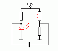
How does this circuit work ?
The LED-LDR combination acts as a sort of amplifier.
Increasing the LED-current ("input" signal) lowers the LDR resistance and thereby increases the "output" voltage on the right circuit node.
The capacitor then creates a positive feedback from output to input by having it's charging current running into the LED, that is: as long as the "output" voltage keeps increasing.
When the output voltage reaches a maximum, close to the supply voltage, the charging of the capacitor stops and the LED dims. This causes the LDR resistance to increase and then the output voltage goes down. The LED now shuts off completely (via the charged capacitor). The left resistor drives a small current that slowly makes the LED getting slightly positive biased again, discharging the capacitor. The LED intensity increases and the cycle repeats itself.
This type of oscillator is called a "relaxation oscillator".
For having enough gain to get the oscillator running, a high intensity LED should be used , facing the LDR within 5mm. The red LED used in this circuit was model OVLBR4C7, intensity specified as 3700 mcd @20mA.
When blinking in the dark, enough stray light is left to clearly see the LED flashing, as demonstrated in the demo movie (link provided).
In high ambient light conditions the LDR remains in low resistance state so the "output" voltage stays permantly high and the LED remains at a very low current bias without blinking.
Diskussion (5 Kommentare)