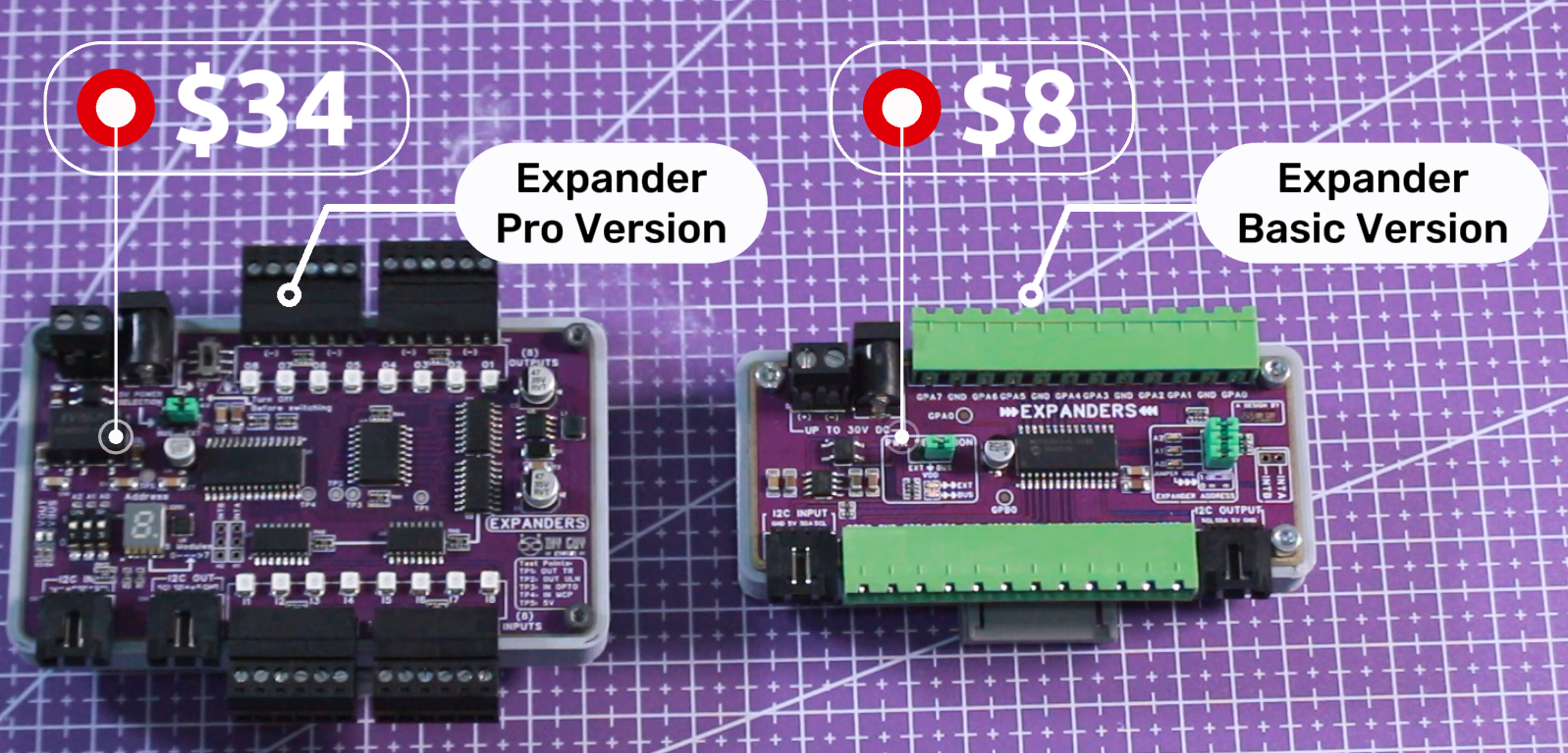
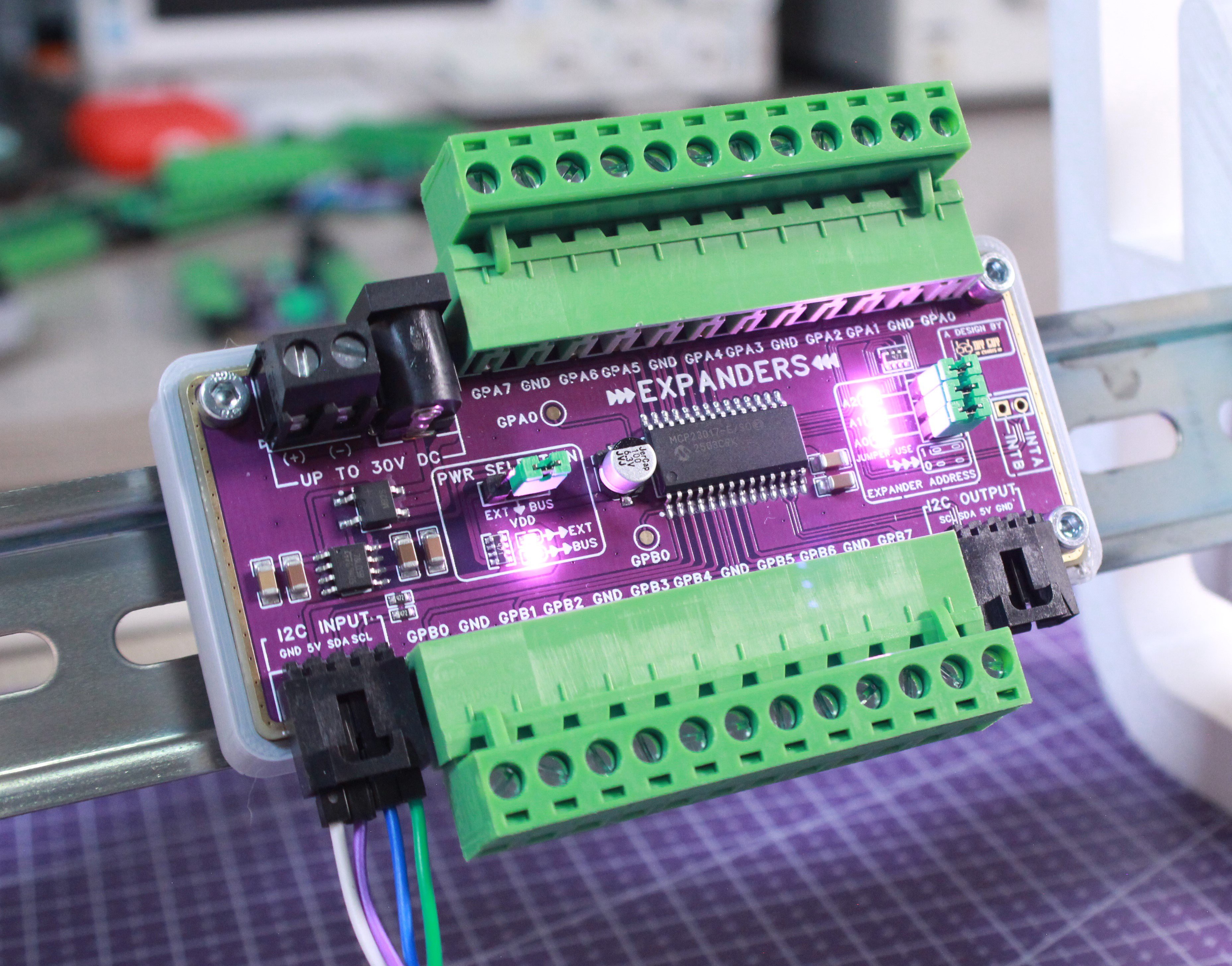
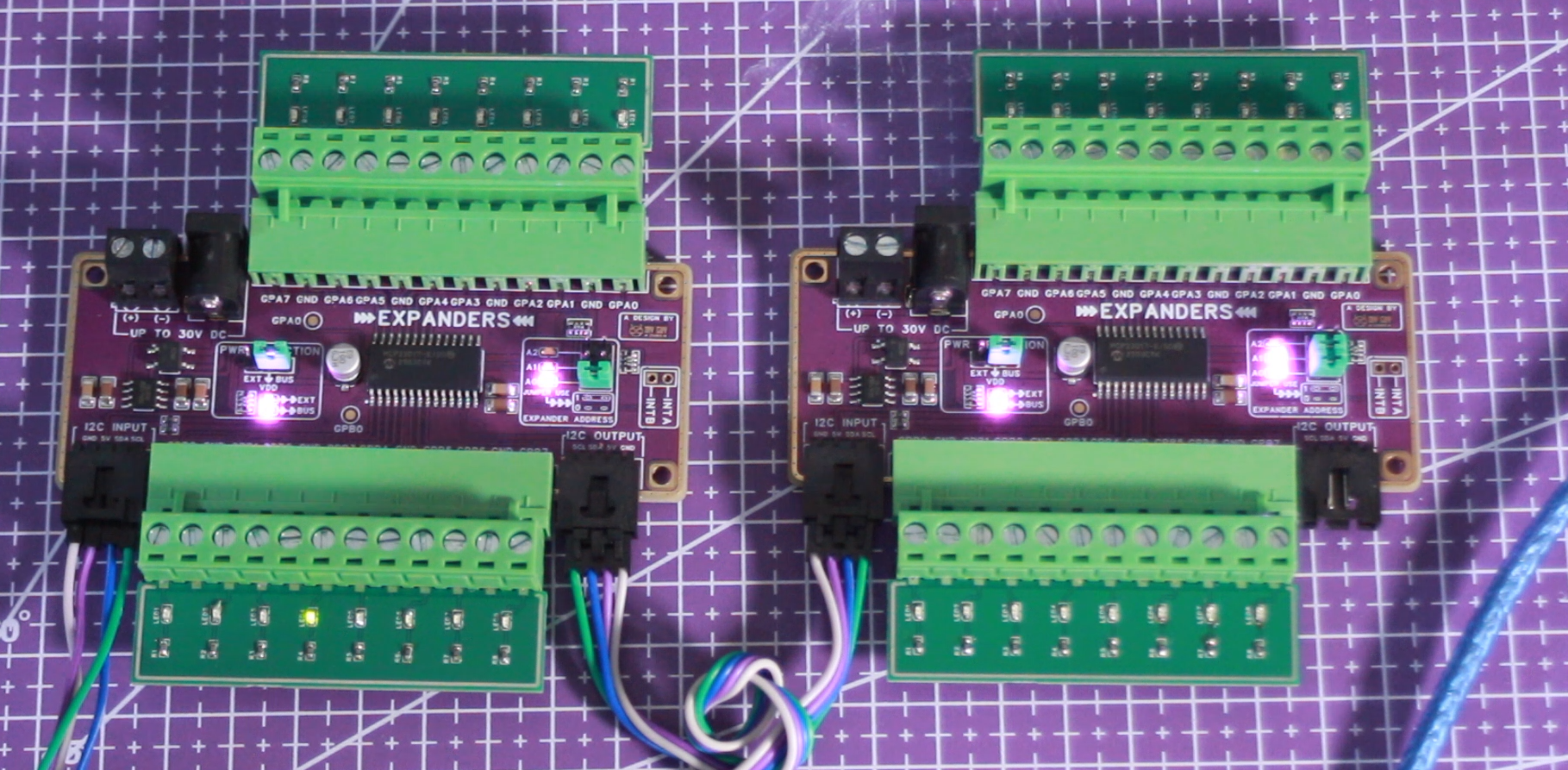
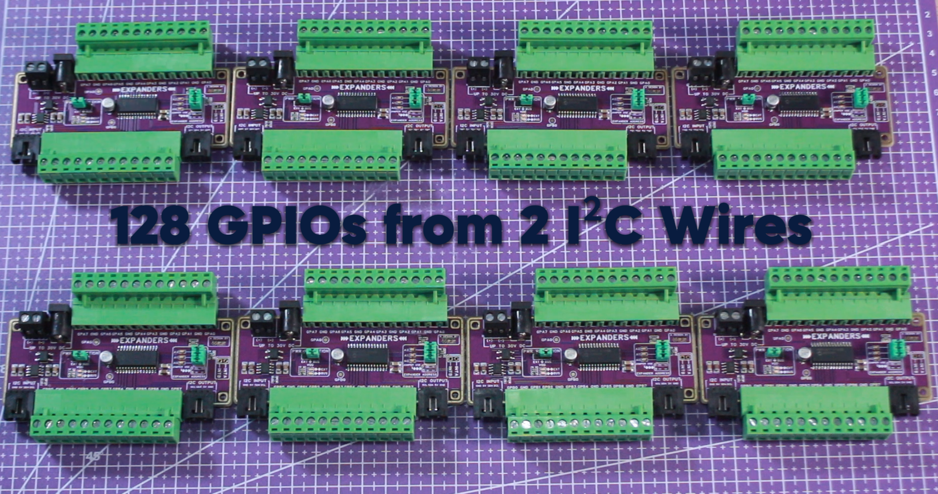
A simpler, budget-friendly 16-channel GPIO expander based on the MCP23017. Perfect for hobbyists, prototyping, and educational projects. Chain up to 8 modules for 128 GPIOs controlled via I²C.
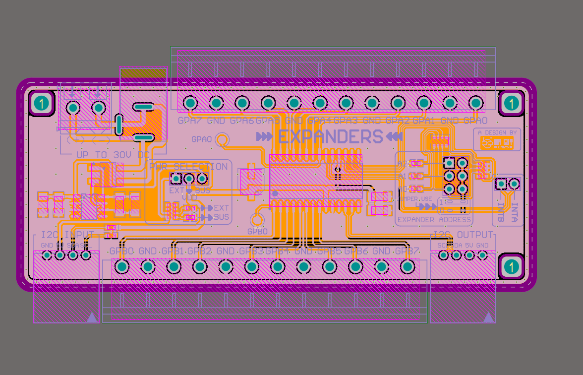
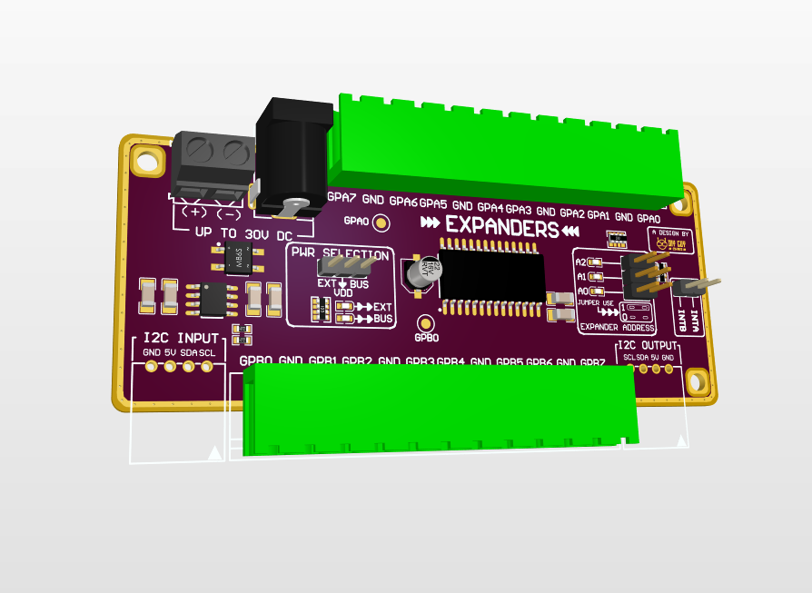
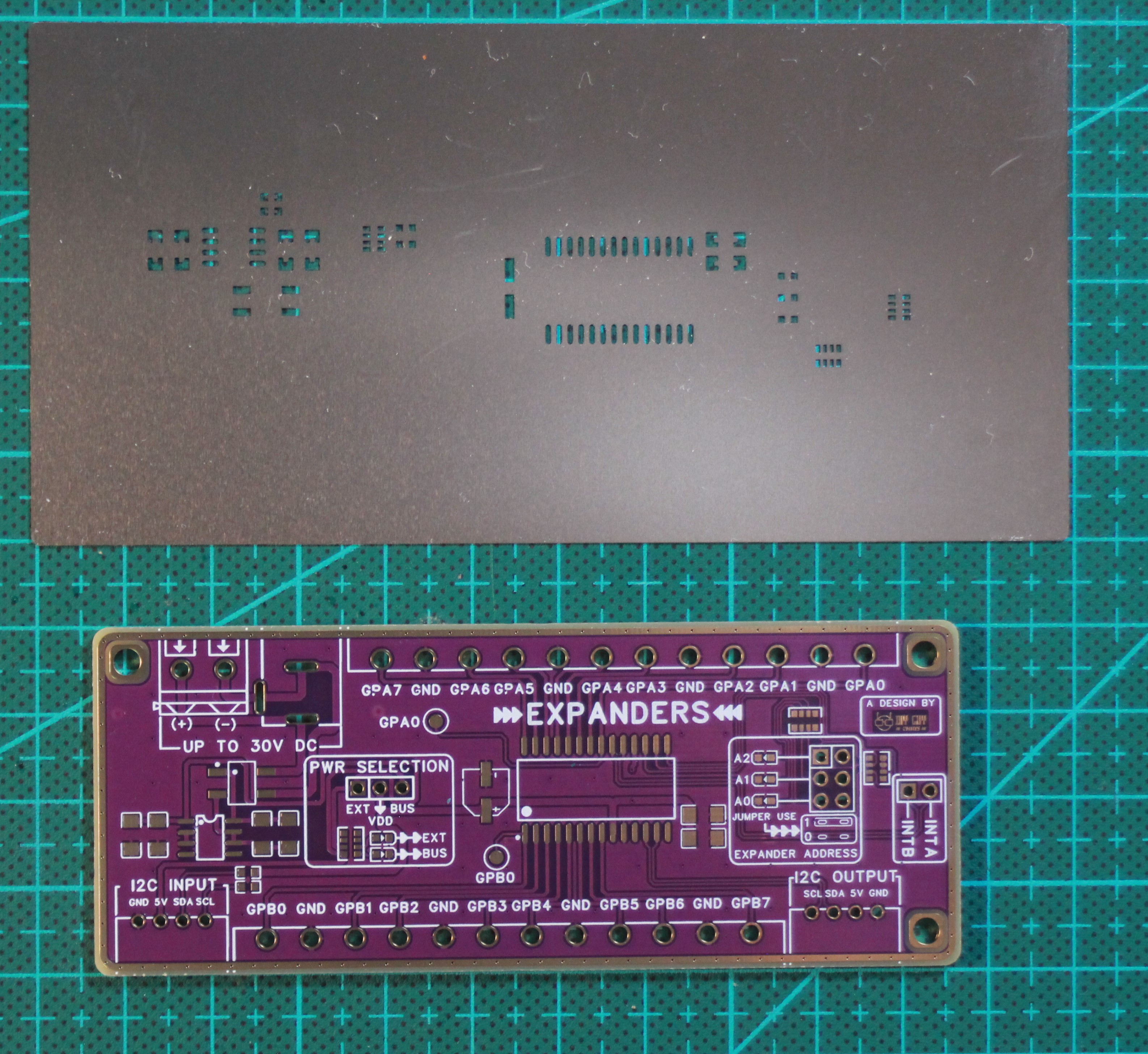
This is a cost-effective alternative to my industrial version, removing expensive components like optocouplers and the ULN2803A driver. The board is compact at 100×40mm, fitting JLCPCB's $2 special offer, and uses larger 5mm terminal blocks for easier wiring.
Supplies
Main ICs:
MCP23017 (I²C I/O Expander)
Power:
MB2S (Bridge rectifier)
78L05 (Voltage regulator)
DC Jack connector
Screw terminal (2-pin)
PCB & Assembly:
2-layer PCB (100×40mm)
SMD components (resistors, capacitors, LEDs)
5mm terminal blocks (WJ2EDGK-5.08-12P-14-00A)
3-pin headers for jumpers
I²C connectors (4-pin, 2.54mm)
Optional:
Arduino UNO (for testing)
I²C cables
Soldering tools (hot plate, iron, tweezers)
Schematic Design
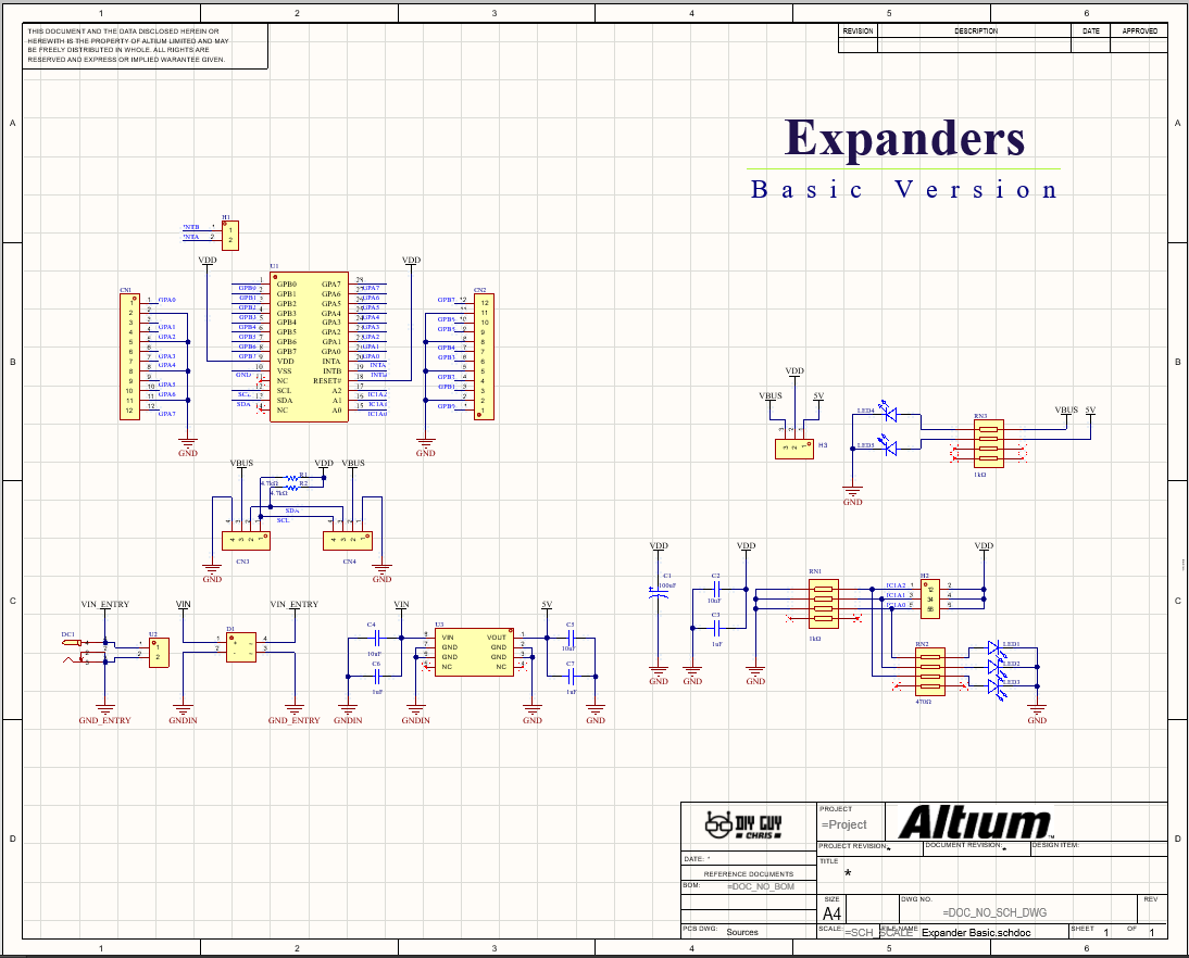
Design the circuit in Altium starting with the power entry. Use a bridge rectifier (MB2S) for reverse polarity protection, followed by a 78L05 linear regulator to step down voltage to 5V.
The MCP23017 connects to the I²C bus. Its 16 GPIO pins are directly connected to terminal blocks, no optocouplers or ULN2803A driver needed for this basic version.
For address selection, use three jumpers connected to the A0, A1, and A2 pins. Three LEDs show the binary address (0-7). Add 1kΩ resistors for the LEDs and 4.7kΩ pull-up resistors for the I²C lines.
Bring your design to life with the Elektor PCB Service, powered by Eurocircuits. Upload the project files and order professionally manufactured PCBs or assembled boards through a proven European production platform.
Supporting KiCad, Eagle, Gerber, and ODB++ formats, the service is suitable for everything from prototypes and validation builds to series production and volume manufacturing.
Das Elektor Magazine gehört seit 65 Jahren zu den führenden Informationsquellen für Elektronikingenieure, Entwickler, Start-ups und Unternehmen. Unser Magazin wird von einer aktiven Community aus Elektronikingenieuren – von Studenten bis zu Profis – getragen, die mit Leidenschaft innovative Ideen entwickeln und teilen.
Für diese veröffentlichen wir jedes Jahr Hunderte von Beiträgen in Formaten wie Artikeln, Videos, Webinaren und weiteren Lernformaten. Unsere Mission ist es, Wissen auf jede mögliche Weise zu teilen und die Leser mit den neuesten Entwicklungen im Bereich der Elektrotechnik zu inspirieren.
Vielen Dank für Ihre Bewertung!
Kommentar hinzufügen
Vielen Dank für Ihre Bewertung!
Möchten Sie einen Kommentar mit Ihrer Bewertung hinterlassen? Bitte melden Sie sich unten an. Nicht gewünscht? Dann schließen Sie einfach dieses Fenster.



Diskussion (0 Kommentare)