
Air and environmental sensor
The project implies usage of several sensors (gas and environmental sensors) to determine if air in a specific zone (indoor or outdoor) is polluted; the values are sent over LoRa to TTN and then viewed in the Datacake application.
Introduction.
The project is build around the Nucleo-WL55JC LoRa board and is divided into several parts:
- end-device + sensors: is build around Nucleo-WL55JC LoRa board, analog VOC sensor and NUCLEO-IKS01A3 sensor board (from ST);
- LoRa gateway: is build with Nucleo-F746ZG development board + LoRa HF BAND(868/915MHz) Gateway expansion board (from RisingHF); this is an KIT from ST:
- TTN server: used to receive data from LoRa end-device and visualize in raw format;
- Datacake IoT platform: used to display the data received from TTN in a nice dashboard.
1. Sensor part.
For VOC sensing I used the following sensor: Fermion MEMS VOC sensor (https://www.dfrobot.com/product-2707.html).This sensor is analogic one and is capable of only quantitative measurements.
The detection range is between 1-500ppm.
The analogic out is connected to CN8 PIN1 from NUCLEO-IKS01A3, Arduino Connector. The +3,3V and GND are connected to CN6, PIN4 and 7, on the same NUCLEO-IKS01A3, Arduino Connector.
For temperature and humidity is used HTS221.
For atmospheric pressure is used LPS22HH.
Both above sensors are digital ones and are connected through I2C1 bus to Nuclkeo-WL55JC LoRa board.
2. Software tools.
To develop the project, I used the following softwares:
- STM32CubeIDE v1.10.0 - https://www.st.com/en/development-tools/stm32cubeide
- STM32CubeMX v6.10.0 - https://www.st.com/en/development-tools/stm32cubemx
- STM32CubeProgrammer v2.15.0 - https://www.st.com/en/development-tools/stm32cubeprog.html
- TeraTerm or similat tool for serial communications;
In order to achive the project, I used an working example for Nucleo-WL55JC LoRa board fron ST and I modified for my needs.
The example is from suite "en.stm32cubewl-v1-3-0.zip" - https://www.st.com/en/embedded-software/stm32cubewl.html
The code is from this path: "en.stm32cubewl-v1-3-0\STM32Cube_FW_WL_V1.3.0\Projects\NUCLEO-WL55JC\Applications\LoRaWAN\LoRaWAN_End_Node".
3. Setup the SW and HW.
To achive the setup and test the example from ST, I used the following presentations:
1. https://www.youtube.com/watch?v=vuc6914B0KM - overview of loRaWAN with STM32WL and LoRa Gateway: The Things Stack, LoRaWAN gateway kit;
2. https://www.youtube.com/watch?v=uJU3YM1MWN4 - setup LoRaWAN gateway with EU settings (according to documentation um2587-getting-started-with-the-pnucleolrwan2-and-pnucleolrwan3-starter-packs-stmicroelectronics, page 30 to 33), setup acccount on The Things Network (gateway from LoRa and internet) and connect LoRa gateway to TTN with EU settings;
3. https://www.youtube.com/watch?v=8KNfrWoa1fw&t=430s - setup Nucleo-WL55JC1, connect this board to gateway and TTN, in order to receive data from end-device;
4. https://www.youtube.com/watch?v=JzH11oUi3A0&t=157s - this is partly used, because in the video is presented the "Cayenne", an IoT platform used to develop, store and display the data received in a nice UI. Starting with 31.09.2023, The Cayenne services enter in end-of-life; see here: https://www.thethingsnetwork.org/forum/t/mydevices-cayenne-end-of-life/64654
For this reason, I used other IoT platform to configure a nice UI: Datacake.
5. https://www.youtube.com/watch?v=9s8XiABakuQ&t=303s - this part describe the setting that we have to make in order to use the sensor board IKS01A3. This board contain: temperature, humidity, pressure and other MEMS sensors.
The settings that I have to do in order to transfer the data from end-device to Datacake interface are explained in the next session, spitted in 6 parts.
a). Settings in LoRa Gateway.
The firmware for gateway is provided by ST, from here: https://www.st.com/en/evaluation-tools/p-nucleo-lrwan2.html?ecmp=tt21915_us_social_jun2021
It is used the firmware specific for TTN: https://www.st.com/en/partner-products-and-services/the-things-network-gateway-firmware.html
After the firmware was flashed in the LoRa gateway board, using STN32CubeProgrammer, the following data was set according to Step 3, point 1:
Set MAC address for gateway: AT+MAC=xxxxxxxxxxxx --> this is board specific and is written on the board label;
Set channels used for my region, Ro, EUI (from specification from Step3, point 1:
AT+CH=EU868
AT+CH=0,867.1,A
AT+CH=1,867.3,A
AT+CH=2,867.5,A
AT+CH=3,867.7,A
AT+CH=4,867.9,B
AT+CH=5,868.1,B
AT+CH=6,868.3,B
AT+CH=7,868.5,B
AT+CH=8,868.3,B,7,250
AT+CH=9,868.8
Set the packet forwarder to EU network:
AT+PKTFWD=eu1.cloud.thethings.network,1700,1700
Reset gateway in order to apply the settings
AT+RESET
After that, the gateway should be connected to a LAM network and then, after few seconds, will present in TTM network as connect; see picture...
b). Setup the end-node.
The example used for this project is located in the folder "en.stm32cubewl-v1-3-0", path: en.stm32cubewl-v1-3-0\STM32Cube_FW_WL_V1.3.0\Projects\NUCLEO-WL55JC\Applications\LoRaWAN\LoRaWAN_End_Node
This path should be opened from STM32CubeIDE v1.10.0.
Obs here: all the modifications presented in video from Step3 point 3 are already done in the example version; the only modification that we have to made is this: in file sys_conf.h, at line 78, set DEBUGGER_ENABLED 1, as in picture "Debug mode ON.png".
Flash the end-node from STM32CubeIDE and follow the instructions from video (from Step 3, point 3).
To register the end-node into TTM, use settings for EUI and MAC address from the sticker from the board.
The settings for end-device used ate from the picture "End-device settings.png".
After that, wait until the end-device will connect to gateway and the data will appeare in TTN , End device Live data window, as in the attached picture "". Moreover, the data sent by the end-devive can be monitored in TTN, in Gateway section, Live data, as in the attached picture: "Data receided by the gateway.png".
c). Setup Datacake.
In order to receive data in a nice dashboard, I used Datacake IoT platform. This platform can create a nice dashboard for mobile phones, along the dashboards for PC.
Note: I used this platform because Cayenne is no more available (I wrote this at point 3, Setup SW and HW, step 4).
First, in TTN, we have to go to Webhooks, and from there we have to create an webhook by pressing on "Add Webhook", choosing Datacake, set the webhook ID and pressing on "Creating Datacake webhook" button.
From Datacake, goto Integration and select Webhooks; from there, press on "Add Webhook", complete Endpoint URLK with the link from TTN, write something at description and then press on "Create webhook".
Then, goto "Devices", press on "Add device", choose LoRaWAN, Choose New product, (because these ST dev boards are not included in the Datacake device list), set a product name, select network server as "The Things Stack V3",set the end-device EUI (from TTN setup), set a device name, location (optional) and then select a plan for the data usage (for this project I selected Free plan, with 7 dayd data retention and 500 datapoints per day) and press "Add 1 device".
Now, in this moment, we have set the connection between TTN and Datacake. but all the data transfered need to be visualized in datacake dashboard. but for that, we need to "decode" them, from the received payload. For that, we have to create a "decoder".
To create a decoder, we have to know the data structure, for that, we need to look into STM32CubeIDE, file lora_app.c, lines from 601: from there the payload structure start at the line 601 with byte0 (used for LED status on or off); continue with pressure value (high value and low value), temperature, humidity (the same as for pressure, high and low values), position (latitude and longitude - are set to a ST fix position), altitude (based on GPS module; is set to 0 for this example) and VOC sensor value (this is not in the original example, I will explain later); for that, see attached picture named "STM32CubeIDE lora_app payload format.png".
Now, let's set the decoder in Datacake. For that, go to in devices, select the end node and then press on Configuration; from there, go down until the "payload decoder". here, you can copy and paste the information from attached decoder (named "Payload decoder for datacake.txt"). in the end, this should be like in the attached pictures "Datacake decoder_1.png" and "Datacake decoder_2.png".
In this moment, we are ready to create the nice dashboard. For that, we have to go in Datacake, Devices, Dashboar and from here, we have to set the Dashboard in edit mode, as in the picture "Datacake dashboard edit mode.png". After the desktop dashboars is set, then we can create a dashboard for mobile, as in the picture "Datacake dashboard edit mode for mobile.png".
In this moment, the whole flow, from end-device to distant PC or mobile is completed.
d). Adding the ST NUCLEO-IKS01A3 sensors board and analog VOC sensor
Until this point, we tested the link using an example provided by ST.
Now, we have to modify this example and add the temperature, humidity, pressure and VOC sensor to the project in order to read, transmit and display the real data.
In order to setup the NUCLEO-IKS01A3 , the video named "LoRaWAN with STM32 Getting Started: Part 5, IKS01A3 Sensor Shield Integration - STM32CubeIDE (youtube.com)" it is very usefull.
After the board is set, the end-device is flashed and the real data from sensors are received in datacake dashboard, we have to set the VOC gas sensor.
The VOC sensor used for this project is " GM-502B MEMSVOCGasSensor ", from DFRobot: VOC sensor
The datasheet of this sensor is attached to the project.
This is an analogic sensor; the output is proportional with the quantitativ measurement of VOC gas concentration. The working voltade of this sensor is 3,3V, the same as used by the end-device board, Nucleo-WL55JC LoRa board.In order to read the ADC, we have to configure the ADC input using the STM32CubeMX.
From STM32CubeMX, in the ADC section, I activated the ADC input for IN1, IN3 and IN5. But, the IN1 and IN3 are multiplexed with I2C3_SDA I acn use only the IN5.
OBS: the IN1 and IN3 ate multiplexed with I2C3 comunicvation net, but, because I used the NUCLEO-IKS01A3, the pull-up resistors for I2C protocon are soldered on the board; in this case, the ADC will read anways 3,3V.
After that, go to in Project manager, setup/verify the Project and Code generatot tabs, as in presented in the video from the begining of this section and press on Generate code.
The settings for ADC are shown in pictures: "Set ADC in STM32CubeMX_01.png" and "Set ADC in STM32CubeMX_02.png".
Now, open the generated project using STM32CobeIDE, and add and modify the following files:
- locate file adc_if.c; at the line 76, add the following code:uint16_t Read_ADC5_value(void) { uint16_t ADC5_value = ADC_ReadChannels(ADC_CHANNEL_5); return ADC5_value; }- locate file lora_app.c; at line 630, add the following code: - locate file lora_app.c; at line 630, add the following code: AppData.Buffer[i++] = (uint8_t)((Read_ADC5_value() >>8) & 0xFF); AppData.Buffer[i++] = (uint8_t)(Read_ADC5_value() & 0xFF);OBS: the ADC is set for 12bits; the result is read on 10 bits; the result is splitted into low value (last 8 bits) and high value (first 2 bits); this result is added to the payload to be sent over LoRa;
- locate file lora_app.h; at the line 54, modify the value to sent the data with a rate of 1 minute instead 10 seconds, as in the original example:
#define APP_TX_DUTYCYCLE 60000 //10000
- locate file sys_conf.h; hete, verify/modify the following lines:
line 45: #define SENSOR_ENABLED 1 //0 - enable the NUCLEO-IKS01A3 sensor board;
line 78: #define DEBUGGER_ENABLED 1 //0 - enable debugger;
line 84: #define LOW_POWER_DISABLE 1 //0 - activate sleep mode
After that, compile and flash the end-device.
if everythigh is good, soon the data from sensors board and VOC will be available in TTN and in Datacake dashboards (PC and Mobile too).
Several screenshots from TTN and Datacake dashboards (pc and Mobile) are attached: "Data sent by End-device and received in TTN.png", "Data on Datacake Dashboard.png", "Data on Datacake mobile dashboard.png".
e). Power supply
For LoRaWan gateway, I used two power adapters with 5V/1A each and, for testing, an battery charger with two outputs, for 5V/1A..
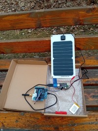
For End-device, because was created as portable device, I used an mixed solar and USB charger. The power supply for end-device consist in one solar panel, one MPTT charger and one Li-Ion accumulator with 3,7V/1200mA.
The current consumption of end-device, in normal operation, is around 80mA.
The solar charger+solar power: https://www.dfrobot.com/product-2000.html
f). Working
The working flow is this: the end-device, powered by solar panel and accumulator, is placed distant from gateway (and near a zone with possible poluted air); the data are sent from end-devive, through gateway to TTN server and ther forwarded to Datacake; from here, in the Datacake dashboard, the data are visualized; moreover, the dara cam ve visualized anywhere in the world, using Datacake mobile app.
Data are sent from end-device do TTN with a rate at 1 minute.
In order to demonstrare the working project, I attached 3 videos:
- Starting LoRaWAN gateway;
- Data flow from End-device to Datacake (part 1 and oart 2);
- End-device powered from solar panel (part 1 and oart 2).
OBS: the resolution of attached video is low;
Below you will find links from Yoputube, where the video quality is better:
- Starting LoRaWAN gateway - https://youtu.be/MA_7QM-If4E
- Data flow from End-device to Datacake - https://youtu.be/aMeN31rz17Y
- End-device powered from solar panel - https://youtu.be/4lksjW4a85M
Because the whole dobe for this project is to big to be attached here, I will upload only the modified files, with nthe specific path:
- file "adc_if.h" will be copied here: STM32Cube_FW_WL_V1.3.0\Projects\NUCLEO-WL55JC\Applications\LoRaWAN\LoRaWAN_End_Node\Core\Inc
- file "adc_if.c" will be copied here: STM32Cube_FW_WL_V1.3.0\Projects\NUCLEO-WL55JC\Applications\LoRaWAN\LoRaWAN_End_Node\Core\Src
- file "lora_app.h" and "lora_app.c" will be copied here: STM32Cube_FW_WL_V1.3.0\Projects\NUCLEO-WL55JC\Applications\LoRaWAN\LoRaWAN_End_Node\LoRaWAN\App
- file "sys_config.h" will be copied here: STM32Cube_FW_WL_V1.3.0\Projects\NUCLEO-WL55JC\Applications\LoRaWAN\LoRaWAN_End_Node\Core\Inc
OBS: all these files will be copied after the project was modified using STM32CubeMX.
All above files are contained in the attached archive, named: "Project_code_filesf.zip"
4. Next steps.
The possible improvements that can be done:
- attach the X-Nucleo-GNSS1 (based on TESEO-LIV3 GNSS) module, in order to have a valid GPS position on the sensor;
- activate the accelerometer, from NUCLEO-IKS01A3, in order to verify if the sensor was moved from the location;
- set a downlink comunication with end-device, from Datacake, in order to activare an alarm if the sensor is moved or read the sensor ar request;
The project is build around the Nucleo-WL55JC LoRa board and is divided into several parts:
- end-device + sensors: is build around Nucleo-WL55JC LoRa board, analog VOC sensor and NUCLEO-IKS01A3 sensor board (from ST);
- LoRa gateway: is build with Nucleo-F746ZG development board + LoRa HF BAND(868/915MHz) Gateway expansion board (from RisingHF); this is an KIT from ST:
- TTN server: used to receive data from LoRa end-device and visualize in raw format;
- Datacake IoT platform: used to display the data received from TTN in a nice dashboard.
1. Sensor part.
For VOC sensing I used the following sensor: Fermion MEMS VOC sensor (https://www.dfrobot.com/product-2707.html).This sensor is analogic one and is capable of only quantitative measurements.
The detection range is between 1-500ppm.
The analogic out is connected to CN8 PIN1 from NUCLEO-IKS01A3, Arduino Connector. The +3,3V and GND are connected to CN6, PIN4 and 7, on the same NUCLEO-IKS01A3, Arduino Connector.
For temperature and humidity is used HTS221.
For atmospheric pressure is used LPS22HH.
Both above sensors are digital ones and are connected through I2C1 bus to Nuclkeo-WL55JC LoRa board.
2. Software tools.
To develop the project, I used the following softwares:
- STM32CubeIDE v1.10.0 - https://www.st.com/en/development-tools/stm32cubeide
- STM32CubeMX v6.10.0 - https://www.st.com/en/development-tools/stm32cubemx
- STM32CubeProgrammer v2.15.0 - https://www.st.com/en/development-tools/stm32cubeprog.html
- TeraTerm or similat tool for serial communications;
In order to achive the project, I used an working example for Nucleo-WL55JC LoRa board fron ST and I modified for my needs.
The example is from suite "en.stm32cubewl-v1-3-0.zip" - https://www.st.com/en/embedded-software/stm32cubewl.html
The code is from this path: "en.stm32cubewl-v1-3-0\STM32Cube_FW_WL_V1.3.0\Projects\NUCLEO-WL55JC\Applications\LoRaWAN\LoRaWAN_End_Node".
3. Setup the SW and HW.
To achive the setup and test the example from ST, I used the following presentations:
1. https://www.youtube.com/watch?v=vuc6914B0KM - overview of loRaWAN with STM32WL and LoRa Gateway: The Things Stack, LoRaWAN gateway kit;
2. https://www.youtube.com/watch?v=uJU3YM1MWN4 - setup LoRaWAN gateway with EU settings (according to documentation um2587-getting-started-with-the-pnucleolrwan2-and-pnucleolrwan3-starter-packs-stmicroelectronics, page 30 to 33), setup acccount on The Things Network (gateway from LoRa and internet) and connect LoRa gateway to TTN with EU settings;
3. https://www.youtube.com/watch?v=8KNfrWoa1fw&t=430s - setup Nucleo-WL55JC1, connect this board to gateway and TTN, in order to receive data from end-device;
4. https://www.youtube.com/watch?v=JzH11oUi3A0&t=157s - this is partly used, because in the video is presented the "Cayenne", an IoT platform used to develop, store and display the data received in a nice UI. Starting with 31.09.2023, The Cayenne services enter in end-of-life; see here: https://www.thethingsnetwork.org/forum/t/mydevices-cayenne-end-of-life/64654
For this reason, I used other IoT platform to configure a nice UI: Datacake.
5. https://www.youtube.com/watch?v=9s8XiABakuQ&t=303s - this part describe the setting that we have to make in order to use the sensor board IKS01A3. This board contain: temperature, humidity, pressure and other MEMS sensors.
The settings that I have to do in order to transfer the data from end-device to Datacake interface are explained in the next session, spitted in 6 parts.
a). Settings in LoRa Gateway.
The firmware for gateway is provided by ST, from here: https://www.st.com/en/evaluation-tools/p-nucleo-lrwan2.html?ecmp=tt21915_us_social_jun2021
It is used the firmware specific for TTN: https://www.st.com/en/partner-products-and-services/the-things-network-gateway-firmware.html
After the firmware was flashed in the LoRa gateway board, using STN32CubeProgrammer, the following data was set according to Step 3, point 1:
Set MAC address for gateway: AT+MAC=xxxxxxxxxxxx --> this is board specific and is written on the board label;
Set channels used for my region, Ro, EUI (from specification from Step3, point 1:
AT+CH=EU868
AT+CH=0,867.1,A
AT+CH=1,867.3,A
AT+CH=2,867.5,A
AT+CH=3,867.7,A
AT+CH=4,867.9,B
AT+CH=5,868.1,B
AT+CH=6,868.3,B
AT+CH=7,868.5,B
AT+CH=8,868.3,B,7,250
AT+CH=9,868.8
Set the packet forwarder to EU network:
AT+PKTFWD=eu1.cloud.thethings.network,1700,1700
Reset gateway in order to apply the settings
AT+RESET
After that, the gateway should be connected to a LAM network and then, after few seconds, will present in TTM network as connect; see picture...
b). Setup the end-node.
The example used for this project is located in the folder "en.stm32cubewl-v1-3-0", path: en.stm32cubewl-v1-3-0\STM32Cube_FW_WL_V1.3.0\Projects\NUCLEO-WL55JC\Applications\LoRaWAN\LoRaWAN_End_Node
This path should be opened from STM32CubeIDE v1.10.0.
Obs here: all the modifications presented in video from Step3 point 3 are already done in the example version; the only modification that we have to made is this: in file sys_conf.h, at line 78, set DEBUGGER_ENABLED 1, as in picture "Debug mode ON.png".
Flash the end-node from STM32CubeIDE and follow the instructions from video (from Step 3, point 3).
To register the end-node into TTM, use settings for EUI and MAC address from the sticker from the board.
The settings for end-device used ate from the picture "End-device settings.png".
After that, wait until the end-device will connect to gateway and the data will appeare in TTN , End device Live data window, as in the attached picture "". Moreover, the data sent by the end-devive can be monitored in TTN, in Gateway section, Live data, as in the attached picture: "Data receided by the gateway.png".
c). Setup Datacake.
In order to receive data in a nice dashboard, I used Datacake IoT platform. This platform can create a nice dashboard for mobile phones, along the dashboards for PC.
Note: I used this platform because Cayenne is no more available (I wrote this at point 3, Setup SW and HW, step 4).
First, in TTN, we have to go to Webhooks, and from there we have to create an webhook by pressing on "Add Webhook", choosing Datacake, set the webhook ID and pressing on "Creating Datacake webhook" button.
From Datacake, goto Integration and select Webhooks; from there, press on "Add Webhook", complete Endpoint URLK with the link from TTN, write something at description and then press on "Create webhook".
Then, goto "Devices", press on "Add device", choose LoRaWAN, Choose New product, (because these ST dev boards are not included in the Datacake device list), set a product name, select network server as "The Things Stack V3",set the end-device EUI (from TTN setup), set a device name, location (optional) and then select a plan for the data usage (for this project I selected Free plan, with 7 dayd data retention and 500 datapoints per day) and press "Add 1 device".
Now, in this moment, we have set the connection between TTN and Datacake. but all the data transfered need to be visualized in datacake dashboard. but for that, we need to "decode" them, from the received payload. For that, we have to create a "decoder".
To create a decoder, we have to know the data structure, for that, we need to look into STM32CubeIDE, file lora_app.c, lines from 601: from there the payload structure start at the line 601 with byte0 (used for LED status on or off); continue with pressure value (high value and low value), temperature, humidity (the same as for pressure, high and low values), position (latitude and longitude - are set to a ST fix position), altitude (based on GPS module; is set to 0 for this example) and VOC sensor value (this is not in the original example, I will explain later); for that, see attached picture named "STM32CubeIDE lora_app payload format.png".
Now, let's set the decoder in Datacake. For that, go to in devices, select the end node and then press on Configuration; from there, go down until the "payload decoder". here, you can copy and paste the information from attached decoder (named "Payload decoder for datacake.txt"). in the end, this should be like in the attached pictures "Datacake decoder_1.png" and "Datacake decoder_2.png".
In this moment, we are ready to create the nice dashboard. For that, we have to go in Datacake, Devices, Dashboar and from here, we have to set the Dashboard in edit mode, as in the picture "Datacake dashboard edit mode.png". After the desktop dashboars is set, then we can create a dashboard for mobile, as in the picture "Datacake dashboard edit mode for mobile.png".
In this moment, the whole flow, from end-device to distant PC or mobile is completed.
d). Adding the ST NUCLEO-IKS01A3 sensors board and analog VOC sensor
Until this point, we tested the link using an example provided by ST.
Now, we have to modify this example and add the temperature, humidity, pressure and VOC sensor to the project in order to read, transmit and display the real data.
In order to setup the NUCLEO-IKS01A3 , the video named "LoRaWAN with STM32 Getting Started: Part 5, IKS01A3 Sensor Shield Integration - STM32CubeIDE (youtube.com)" it is very usefull.
After the board is set, the end-device is flashed and the real data from sensors are received in datacake dashboard, we have to set the VOC gas sensor.
The VOC sensor used for this project is " GM-502B MEMSVOCGasSensor ", from DFRobot: VOC sensor
The datasheet of this sensor is attached to the project.
This is an analogic sensor; the output is proportional with the quantitativ measurement of VOC gas concentration. The working voltade of this sensor is 3,3V, the same as used by the end-device board, Nucleo-WL55JC LoRa board.In order to read the ADC, we have to configure the ADC input using the STM32CubeMX.
From STM32CubeMX, in the ADC section, I activated the ADC input for IN1, IN3 and IN5. But, the IN1 and IN3 are multiplexed with I2C3_SDA I acn use only the IN5.
OBS: the IN1 and IN3 ate multiplexed with I2C3 comunicvation net, but, because I used the NUCLEO-IKS01A3, the pull-up resistors for I2C protocon are soldered on the board; in this case, the ADC will read anways 3,3V.
After that, go to in Project manager, setup/verify the Project and Code generatot tabs, as in presented in the video from the begining of this section and press on Generate code.
The settings for ADC are shown in pictures: "Set ADC in STM32CubeMX_01.png" and "Set ADC in STM32CubeMX_02.png".
Now, open the generated project using STM32CobeIDE, and add and modify the following files:
- locate file adc_if.c; at the line 76, add the following code:uint16_t Read_ADC5_value(void) { uint16_t ADC5_value = ADC_ReadChannels(ADC_CHANNEL_5); return ADC5_value; }- locate file lora_app.c; at line 630, add the following code: - locate file lora_app.c; at line 630, add the following code: AppData.Buffer[i++] = (uint8_t)((Read_ADC5_value() >>8) & 0xFF); AppData.Buffer[i++] = (uint8_t)(Read_ADC5_value() & 0xFF);OBS: the ADC is set for 12bits; the result is read on 10 bits; the result is splitted into low value (last 8 bits) and high value (first 2 bits); this result is added to the payload to be sent over LoRa;
- locate file lora_app.h; at the line 54, modify the value to sent the data with a rate of 1 minute instead 10 seconds, as in the original example:
#define APP_TX_DUTYCYCLE 60000 //10000
- locate file sys_conf.h; hete, verify/modify the following lines:
line 45: #define SENSOR_ENABLED 1 //0 - enable the NUCLEO-IKS01A3 sensor board;
line 78: #define DEBUGGER_ENABLED 1 //0 - enable debugger;
line 84: #define LOW_POWER_DISABLE 1 //0 - activate sleep mode
After that, compile and flash the end-device.
if everythigh is good, soon the data from sensors board and VOC will be available in TTN and in Datacake dashboards (PC and Mobile too).
Several screenshots from TTN and Datacake dashboards (pc and Mobile) are attached: "Data sent by End-device and received in TTN.png", "Data on Datacake Dashboard.png", "Data on Datacake mobile dashboard.png".
e). Power supply
For LoRaWan gateway, I used two power adapters with 5V/1A each and, for testing, an battery charger with two outputs, for 5V/1A..
For End-device, because was created as portable device, I used an mixed solar and USB charger. The power supply for end-device consist in one solar panel, one MPTT charger and one Li-Ion accumulator with 3,7V/1200mA.
The current consumption of end-device, in normal operation, is around 80mA.
The solar charger+solar power: https://www.dfrobot.com/product-2000.html
f). Working
The working flow is this: the end-device, powered by solar panel and accumulator, is placed distant from gateway (and near a zone with possible poluted air); the data are sent from end-devive, through gateway to TTN server and ther forwarded to Datacake; from here, in the Datacake dashboard, the data are visualized; moreover, the dara cam ve visualized anywhere in the world, using Datacake mobile app.
Data are sent from end-device do TTN with a rate at 1 minute.
In order to demonstrare the working project, I attached 3 videos:
- Starting LoRaWAN gateway;
- Data flow from End-device to Datacake (part 1 and oart 2);
- End-device powered from solar panel (part 1 and oart 2).
OBS: the resolution of attached video is low;
Below you will find links from Yoputube, where the video quality is better:
- Starting LoRaWAN gateway - https://youtu.be/MA_7QM-If4E
- Data flow from End-device to Datacake - https://youtu.be/aMeN31rz17Y
- End-device powered from solar panel - https://youtu.be/4lksjW4a85M
Because the whole dobe for this project is to big to be attached here, I will upload only the modified files, with nthe specific path:
- file "adc_if.h" will be copied here: STM32Cube_FW_WL_V1.3.0\Projects\NUCLEO-WL55JC\Applications\LoRaWAN\LoRaWAN_End_Node\Core\Inc
- file "adc_if.c" will be copied here: STM32Cube_FW_WL_V1.3.0\Projects\NUCLEO-WL55JC\Applications\LoRaWAN\LoRaWAN_End_Node\Core\Src
- file "lora_app.h" and "lora_app.c" will be copied here: STM32Cube_FW_WL_V1.3.0\Projects\NUCLEO-WL55JC\Applications\LoRaWAN\LoRaWAN_End_Node\LoRaWAN\App
- file "sys_config.h" will be copied here: STM32Cube_FW_WL_V1.3.0\Projects\NUCLEO-WL55JC\Applications\LoRaWAN\LoRaWAN_End_Node\Core\Inc
OBS: all these files will be copied after the project was modified using STM32CubeMX.
All above files are contained in the attached archive, named: "Project_code_filesf.zip"
4. Next steps.
The possible improvements that can be done:
- attach the X-Nucleo-GNSS1 (based on TESEO-LIV3 GNSS) module, in order to have a valid GPS position on the sensor;
- activate the accelerometer, from NUCLEO-IKS01A3, in order to verify if the sensor was moved from the location;
- set a downlink comunication with end-device, from Datacake, in order to activare an alarm if the sensor is moved or read the sensor ar request;
Diskussion (0 Kommentare)